10
1.8. Component Functions
1.8.1. Charge Compensator
The charge compensator included in the Installation and Piping kit as shown in
“Figure 17. Typical Installation (Horizontal Air Handler Shown)” on page 18
servestomaintaintheproperamountofrefrigerantcirculatingincertainsystems.
(Some systems do not require a charge compensator, but do require a similar
Installation and Piping kit to connect into the system [see Product Specications]).
The charge compensator stores excess refrigerant when the Humiditrol coil is
active(dehumidifying)andreturnsittothesystemduringnormalcoolingorheating
operations.WhentheHumiditrolcoilisactive,lesschargeisrequiredtoobtainthe
properamountofsub-coolingbecauseoftheadditionalcoilsurfaceandthecooler
airwhichpassesovertheHumiditrolcoil.
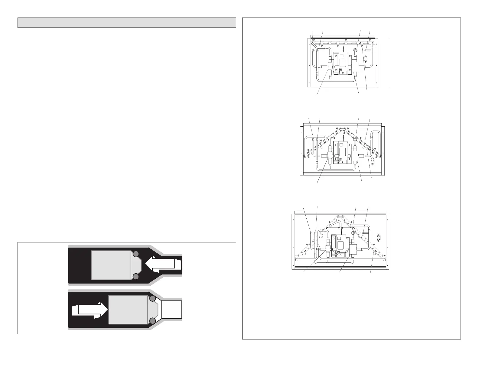
1.8.2. Check/Flow Restrictor
The check function of the check/ow restrictor (shown in Figure 9) prevents
refrigerant from owing into the inactive components during times when the
Humiditrolcoilisinactive.Theowrestrictorcontrolstherateofreturnofchargeto
thesystemfromthechargecompensatorandtheHumiditrolcoilwhenthesystem
changesfrom”Humiditrolcoilactive”to”Humiditrolcoilinactive.”
1.8.3. Valve Assembly
The rst valve of the diverting valve assembly (gure 10, E) directs the ow of
refrigeranttoeitherbypasstheHumiditrolcoil(Humiditrolcoilisinactive)orpass
throughtheHumiditrolcoil(Humiditrolcoilisactive).Thesecondvalve(gure10F)
directstheowofrefrigerantbacktotheliquidlinewhentherstvalve(E)allows
owthroughtheHumiditrolcoil.WhentheHumiditrolcoilisinactive,thesecond
valve(F)providesaventpathtothesuctionline,drainingtheHumiditrolcoiland
chargecompensatorofliquidrefrigerant.
O-RING SEALS
CHECK/FLOW
RESTRICTOR
CHECK/FLOW
RESTRICTOR
“FLOATS IN
CHATLEFF
CONNECTOR
GREATER
PRESSURE
EDA
UNIT
GREATER
PRESSURE
EDA
UNIT
FROM
VAPOR
LINE
TEE
FROM
VAPOR
LINE
TEE
Figure 9. Check/Flow Restrictor Operation
EDA-024B
D060-ADE
C630-ADE
3-WAY DIVERTING VALVE ASSEMBLY
HUMIDITROL COIL
3-WAY DIVERTING VALVE ASSEMBLY
A - Liquid Line From Outdoor Unit
B - Liquid Line to Indoor TXV
C - Check/Flow Restrictor to Vapor
Line Te e
AB CD
HUMIDITROL COIL
HUMIDITROL COIL
D - To Charge Compensator side connection (1/4” line must be brazed closed on systems that do not
require the installation of a charge compensator)
E -
HUMIDITROL inactive mode - bypasses the HUMIDITROL HUMIDITROL active mode - allows
refrigerant flow through
HUMIDITROL
F - HUMIDITROL inactive mode - vent path to suction line; EDA active mode - directs refrigerant flow back to
liquid line.
EF
FE
3-WAY DIVERTING VALVE ASSEMBLY
EF
AB CD
AB CD
Figure 10. Humiditrol Unit Parts Arrangement