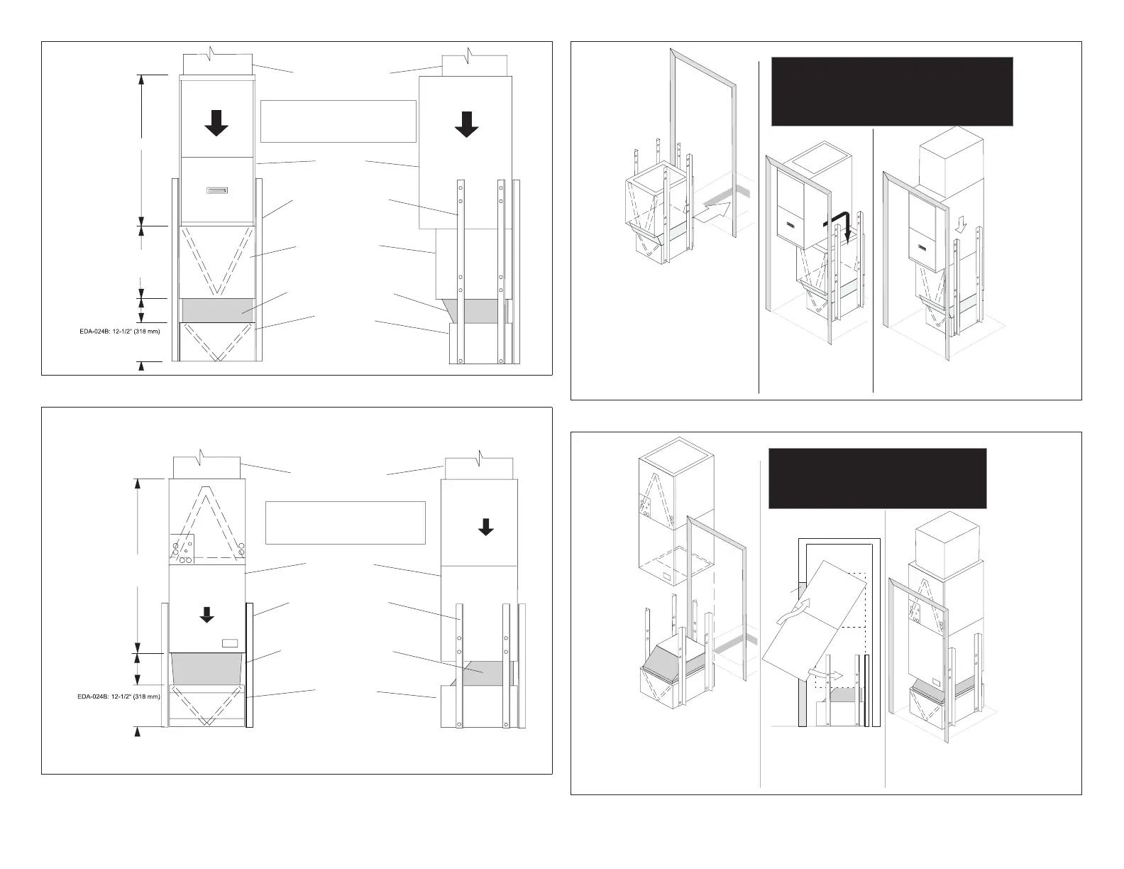
9
EDA−036C: 12−1/2" (318 mm)
EDA−060D: 14" (356 mm)
RETURN AIR PLENUM
FURNACE
FIELD-CONSTRUCTED
SUPPORT STAND
INDOOR COIL UNIT
(INSULATED TRANSITION
HUMIDITROL
UNIT
6" (152 mm) Min.
NOTE − The weight of the indoor coil
and furnace MUST be supported by the
field−contructed support stand − NOT by
transition and Humiditrol coil
VARIES BY INDOOR COIL
MODEL; SEE LENNOX
PRODUCT SPECIFICATION
40 (1016 mm)
Figure 5. Typical Down-ow Furnace
Typical Downflow Air Handler
RETURN AIR PLENUM
AIR HANDLER
FIELD-CONSTRUCTED
SUPPORT STAND
(INSULATED TRANSITION
HUMIDITROL
UNIT
NOTE − The weight of the air handler
MUST be supported by the
field−contructed support stand − NOT by
transition and Humiditrol coil
EDA−036C: 12−1/2" (318 mm)
EDA−060D: 14" (356 mm)
6" (152 mm) Min.
VARIES BY AIR HANDLER
MODEL; SEE LENNOX
PRODUCT SPECIFICATION
FOR DIMENSIONS.
Figure 6. Typical Down-ow Air Handler
Field construct the brackets.
CAUTION! When determining where holes in
the units are to be located and the length of
screws to be used, be sure internal
components will not be jeopardized nor
damaged during assembly.
NOTE − Coil weight must not rest on
transition.
Using the field-constructed brackets, assemble
EDA, transition, and indoor coil, fastening the
brackets to the coil and Humiditrol units with
field−supplied screws.
Move assembled lower package into position (for
example, in the a/c closet).
If location permits, and for better stability, fasten
rear support stand bracket to a wall.
Install and fasten return air plenum to the top
of the unit and secure to wall(s); this will en-
sure the assembly does not tilt forward.
Maneuver furnace into closet, on top
of the coil and between the brackets.
ASSEMBLED HUMIDITROL,
INDOOR COIL AND
TRANSITION
FURNACE
PLENUM
Study the installation site carefully before beginning
installation. These instructions are intended to show a
typical application. Because most sites are different, use
this information as a general guide, making adjustments
if and when necessary, observing all cautions and notes,
and following appropriate ordinances and regulations.
Figure 7. Typical Down-ow Furnace Installation
Field construct the brackets.
CAUTION! When determining where holes in
the units will be located and the length of
screws to be used, be sure internal
components will not be jeopardized nor
damaged during assembly.
NOTE − Air handler weight must not rest on
transition.
Using the field-constructed brackets, assemble the
Humiditrol and transition. If the height of the
opening permits, assemble the air handler as well.
PLENUM
Install and fasten return air plenum to the
top of the unit and secure to wall(s); this
will ensure the assembly does not tilt for-
ward.
If the opening’s height will not accomodate
the entire assembly, move the bottom part
in first, then the air handler. Until it is prop-
erly fastened, be sure to support the weight
of the air handler so that it does not rest on
the transition.
If location permits, and for better stability,
fasten rear support stand bracket to a wall.
Study the installation site carefully before beginning
installation. These instructions are intended to show a
typical application. Because most sites are different, use
this information as a general guide, making adjustments
if and when necessary, observing all cautions and notes,
and following appropriate ordinances and regulations.
CUTAWAY OF CLOSET
DOOR
OPENING
MOVE TOP OF
AIR HANDLER IN
THEN UP
...THEN ROTATE
BOTTOM END
INTO CLOSET
AIR HANDLER
Figure 8. Typical Down-ow Furnace Installation