19
2.4.2. Leak Testing, Evacuating, Charging
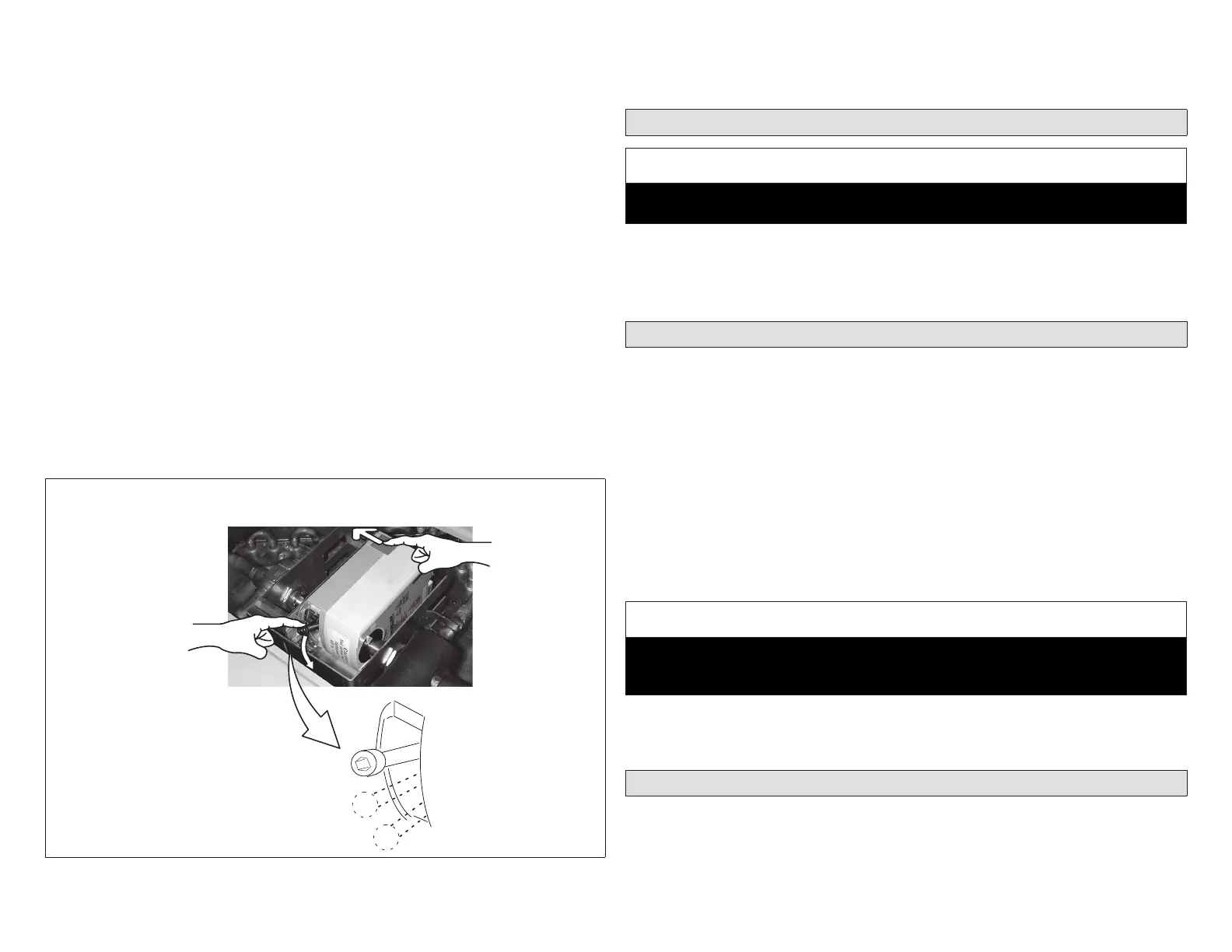
1. Setthe3-waydivertingvalveactuatorshafttothecenter(evacuate)positionfor
leaktestingandevacuationasillustratedinthefollowinggure.IMPORTANT!
TheactuatorshaftmustbesetasdescribedtoallowtheHumiditroltoevacuate
morequickly.
2. Refertoinstructionsprovidedwiththeoutdoorunitforleaktesting,evacuating
andchargingprocedures
3. VerylittlechargeisrequiredfortheadditionalvolumeoftheHumiditrolunit.
Wheninnormalcooling,thecomponentswillallbeoccupiedbyvaporthathas
verylittleweight.Atmost(dependingonthemodel)anadditional1/4poundof
refrigerantmayberequired.
4. When shifting from dehumidify mode to cooling, or vice-versa, wait at least
10minutesforthesystemtoreachstableoperatingpressurebeforechecking
temperaturesandpressures,oradjustingrefrigerantcharge.
NOTE: Prior to starting the outdoor unit for charging, set the thermostat to call for
cooling (dehumidication OFF). It will take about 90 seconds for the 3-way
diverting valve to energize and shift to the cooling position. To ensure
that the 3-way diverting valve is energized and in the “cooling” (forward)
position, observe the position of the 3-way diverting valve actuator shaft
pinch bolt in the following gure; if properly shifted, the pinch bolt will be in
the forward position.
1
2
COOLING
(FORWARD)
EVACUATE
(CENTER)
DEHUMIDIFICATION
(REARWARD)
1. PUSH RED TAB IN DIRECTION INDICATED.
2. PUSH ACTUATOR SHAFT DOWN TOWARD THE
CENTER-OF-TRAV EL POSITION
Figure 19. Setting 3-Way Diverting Valve to Evacuate Position
5. The charge must be checked with the system in cooling operation
(dehumidication OFF). After testing and charging as required, set the
thermostattoforceademandfordehumidication.
2.5. Insulating and Sealing the Unit
IMPORTANT
Allpiping,meteringdevices,andconnectionsmustbeinsulatedtopreventmois-
turedamagecausedbysweating.
Sealthe unitso thatwarm airis not allowed into thecabinet.This isespecially
importantwhentheunitisinstalledinanunconditionedarea.Makesuretheliquid
lineentrypointsaresealedwitheitherrefrigeranttubeinsulatingmaterialorwith
Permagum.
2.6. Other System Components
2.6.1. Blower Control
When Humiditrol units are to be applied with an indoor unit that has a variable
speedmotor(VSM),thenrefertotheindoorunitinstallationinstructionforsetting
blowerspeed.
2.6.2. Thermostat and Sensor
RefertotheComfortSense7500,iComfortE30,M30orS30ThermostatInstallation
andSetupGuidefornon-communicatinginstallation,wiring,andsetup.
NOTE: Lennox communicating outdoor units have an outdoor sensor installed.
If these units are connected to a Lennox communicating thermostat, an
optional outdoor sensor is not needed.
IMPORTANT
EitheraCS7500oriComfortfamilythermostatalongwithaproperlyconnected
outdoortemperaturesensorarerequiredfortheHumiditrolunittofunctionprop-
erly.
Installtheremotesensorontheoutsideofanorthernwallofthehome,awayfrom
directsunlightorotherheatsourcesthatmayaffectitsabilitytoaccuratelysense
outdoortemperature.
2.7. Using Humiditrol Comfort Adjust
IfHumiditrolisenabledintheinstallersettings,thentheHumiditrolAdjustmentin
theUserSettingsaffectsovercoolingoperation(see“Table6.HumiditrolComfort
Adjust Parameters” on page 20 and “Figure 20. Thermostat Operation with
HumiditrolEnabled”onpage20describetheparametersandillustrateHumiditrol
operationundertypicalsettings).