4
lowertemperatureremovingadditionalhumidity.Atthesametime,theHumiditrol
three-wayvalvesrepositionthemselvesandtheHumiditrolcoilbecomesactive.
Thisallowscondenserheattowarmtheindoorairtoavoidexcessiveovercooling
ofthehome.Duringcoolingonly(noHumiditroloperation)theHumiditrolcoilis
inactive.
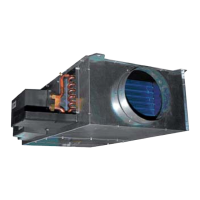
• TheHumiditrolcoilisaddedtoanHVACsystemdownstreamoftheindoorcoil.
Indehumidicationmode,thecoilbecomesanextensionoftheoutdoorcoiland
injectsheatintotheindoorairstream.
• Thisdehumidicationmodeallowssignicantlyimprovedcontrolofthehumidity
intheconditionedspacewithlesschanceofovercoolingthespace.
• The assembly includes a set of 3-way diverting valves which will either route
refrigerantthroughtheHumiditrolcoil,orcausetherefrigeranttobypassthethat
coil,dependingonthemodeofoperation.
1.3.4. Operation Notes
• Dehumidicationwillnotoccurwhentheoutdoortemperatureisatorabove95ºF
orindoortemperatureisatorbelow65ºF.
• Whenoperatingincooling(orheatpumpheating)mode,alltemperaturesand
pressureswillbeasinanormalsystem.
• WhenthethermostatisinHumiditrolmode,andafteracoolingdemandhasbeen
satisedbutadehumidicationdemandpersists,andtheroomtemperatureis
within the MIN, MID, MAX parameters described in Using Humiditrol Comfort
Adjust(see“2.7.UsingHumiditrolComfortAdjust”onpage19),theairhandlers
willoperateatreducedairowwiththecompressorathighspeed.
• When the unit is in the dehumidication mode, the thermostat will display
“dehumidifyoranicon”onthehomescreen.
IMPORTANT
TheCleanAirActof1990banstheintentionalventingofallrefrigerants(CFC,
HFC,andHCFC)asofJuly1,1992.Approvedmethodsofrecovery,recycling
or reclaiming must be followed. Fines and/or incarceration may be levied for
non-compliance
WARNING
Improperinstallation,adjustment,alteration,serviceormaintenancecancause
propertydamage,personalinjuryorlossoflife.
Installation and service must be performed by a licensed professional HVAC
installer(orequivalent)oraserviceagency.
WARNING
Riskofexplosionorre.
Cancauseinjuryordeath.
Recoverallrefrigeranttorelievepressurebeforeopeningthesystem.
1.4. Wiring Diagram Locater
Table 4. Wiring Diagram Locater
Thermostat Indoor Unit Control Outdoor Unit Control Wiring Diagram
ComfortSense 7500 or
iComfort M30
Non-communicating Non-communicating
“Figure11.CS7500
orM30withanyNon-
CommunicatingIndoor
andOutdoorUnits”on
page12.
ComfortSense 7500 or
iComfort M30
Non-communicating
Lennox
Communicating
wiredas24VAC
Conventional
“Figure12.CS7500
orM30withNon-
CommunicatingIndoor
andCommunicating
OutdoorUnits
WiredforNon-
Communicating”on
page13.
ComfortSense 7500 or
iComfort M30
Lennox
Communicatingwired
asnon-communicating
Lennox
Communicatingwired
asnon-communicating
“Figure13.CS7500
orM30with
CommunicatingIndoor
andOutdoorUnits
withBothWiredNon-
Communicating”on
page14.
iComfort E30
Lennox
Communicatingwired
asnon-communicating
Lennox
Communicatingwired
asnon-communicating
“Figure14.E30
withbothIndoor
andOutdoor
Communicating
UnitsWiredforNon-
Communicating”on
page15.
iComfort S30
Lennox
Communicating
Lennox
Communicating
“Figure15.S30
WiredSystemfor
Communicating”on
page16.