Page 10
506270−01 05/09
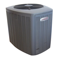
NOTE − SIMILAR INSTALLATION
PRACTICES SHOULD BE USED
IF LINE SET IS TO BE INSTALLED
ON EXTERIOR OF OUTSIDE
WALL.
PVC
PIPE
FIBERGLASS
INSULATION
CAULK
OUTSIDE
WALL
SUCTION LINE
WRAPPED WITH
ARMAFLEX
LIQUID LINE
IMPORTANT! REFRIGERANT
LINES MUST NOT CONTACT
STRUCTURE.
OUTSIDE WALL
LIQUID LINE
SUCTION LINE
IMPORTANT - REFRIGERANT LINES MUST NOT CONTACT WALL.
WOOD BLOCK
BETWEEN STUDS
STRAP
SLEEVE
WOOD BLOCK
STRAP
SLEEVE
WIRE TIE
WIRE TIE
WIRE TIE
INSIDE WALL
Figure 16. Refrigerant Line Set: Installing Vertical
Runs (New Construction Shown)
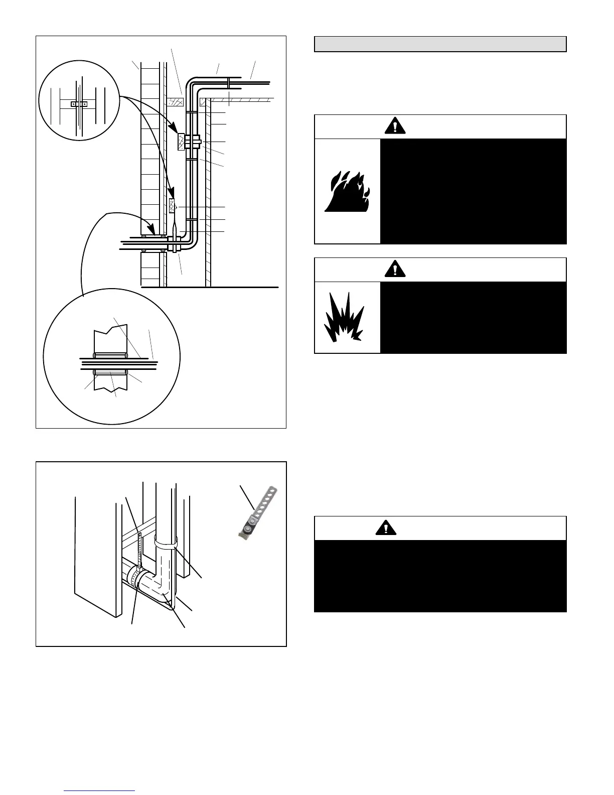
ANCHORED HEAVY NYLON
WIRE TIE OR AUTOMOTIVE
MUFFLER−TYPE HANGER
STRAP LIQUID LINE
TO SUCTION LINE
WALL
STUD
LIQUID LINE
METAL SLEEVE SUCTION LINE − WRAPPED IN
ARMAFLEX
AUTOMOTIVE
MUFFLER-TYPE HANGER
Figure 17. Refrigerant Line Set: Transition from
Vertical to Horizontal
Brazing Connections
Use the following procedure to braze the line set to the new
air conditioner unit. Figure 18 is provided as a general
guide for preparing to braze the line set to the air
conditioner unit.
WARNING
Danger of fire. Bleeding the
refrigerant charge from only the high
side may result in the low side shell
and suction tubing being
pressurized. Application of a brazing
torch while pressurized may result in
ignition of the refrigerant and oil
mixture − check the high and low
pressures before unbrazing.
WARNING
When using a high pressure gas such
as dry nitrogen to pressurize a
refrigeration or air conditioning
system, use a regulator that can
control the pressure down to 1 or 2
psig (6.9 to 13.8 kPa).
1. Cut ends of the refrigerant lines square (free from
nicks or dents). Debur the ends. The pipe must remain
round, do not pinch end of the line.
2. Remove service cap and core from both the suction
and liquid line service ports.
3. Connect gauge low pressure side to liquid line service
valve.
4. To protect components during brazing, wrap a wet
cloth around the liquid line service valve body and
copper tube stub and use another wet cloth
underneath the valve body to protect the base paint.
Also, shield the light maroon R−410A sticker.
WARNING
Polyol ester (POE) oils used with HFC−410A
refrigerant absorb moisture very quickly. It is very
important that the refrigerant system be kept
closed as much as possible. DO NOT remove line
set caps or service valve stub caps until you are
ready to make connections.
5. Flow regulated nitrogen (at 1 to 2 psig) through the
refrigeration gauge set into the valve stem port
connection on the liquid line service valve and out of
the valve stem port connection on the suction service
valve.

 Loading...