Page 11
XP13 SERIES
2
3
4
5
6
outdoor
UNIT
LIQUID LINE
SUCTION LINE
SERVICE
VALVE
SERVICE
VALVE
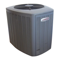
CUT AND DEBUR
ATTACH
GAUGES
WRAP
SERVICE
VALVE
FLOW NITROGEN
NITROGEN
BRAZE LINE SET
1
INSTALL CORE ONLY FOR
BOTH SERVICE PORTS after they
have coolED.
7
INDOOR UNIT
REMOVE CAP AND CORE FROM
BOTH LIQUID AND SUCTION
SERVICE PORTS
SERVICE PORT MUST BE
OPEN TO ALLOW EXIT
POINT FOR NITROGEN
Figure 18. Brazing Connections
NOTE − The RFCIV or TXV metering device at the indoor
unit will allow low pressure nitrogen to flow through the
system.)
NOTE − Use silver alloy brazing rods with five or six percent
minimum silver alloy for copper−to−copper brazing or 45
percent silver alloy for copper−to−brass or copper−to−steel
brazing.
6. Braze the liquid line to the liquid line service valve.
Turn off nitrogen flow. Repeat procedure starting at
paragraph 4 for brazing the suction line to the suction
service valve.
7. After all connections have been brazed, disconnect
manifold gauge set the from service ports, cool down
piping with wet rag and remove all wrappings. Do not
reinstall cores until after evacuation procedure.
Reinstall service caps if desired to close off refrigerant
ports.
Removing Indoor Unit Metering Device
Remove the existing HCFC−22 refrigerant flow control
orifice or thermal expansion valve from the indoor coil. The
existing indoor unit HCFC−22 metering device is not
approved for use with HFC−410A refrigerant and may
prevent proper flushing.
REPLACEMENT PARTS
If replacement parts are necessary for the indoor unit,
order kit 69J46. The kit includes:
10 Brass nuts for liquid line assemblies
20 Teflon rings
10 Liquid line orifice housings
10 Liquid line assemblies
TEFLON RINGS (20)
BRASS NUTS (10)
LIQUID LINE ASSEMBLIES
(INCLUDES STRAINER) (10)
LIQUID LINE ORIFICE HOUSINGS (10)
LIQUID LINE
ASSEMBLY
COPPER
TUBE
PISTON
RETAINER
STRAINER
Figure 19. 69J46 Kit Components
TYPICAL FIXED ORIFICE REMOVAL PROCEDURE
1. On fully cased coils, remove the coil access and
plumbing panels.
2. Remove any shipping clamps holding the liquid line
and distributor assembly.
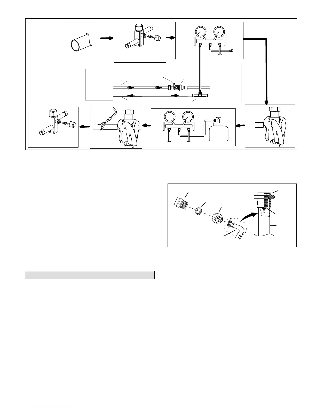
3. Using two wrenches, disconnect liquid line from liquid
line orifice housing. Take care not to twist or damage
distributor tubes during this process.
4. Remove and discard fixed orifice, valve stem
assembly if present and Teflon washer as illustrated in
figure 20.
5. Use a field−provided fitting to temporary reconnect the
liquid line to the indoor unit’s liquid line orifice housing.

 Loading...