Page 17
XP13 SERIES
Electrical
In the U.S.A., wiring must conform with current local codes
and the current National Electric Code (NEC). In Canada,
wiring must conform with current local codes and the current
Canadian Electrical Code (CEC).
Refer to the furnace or blower coil installation instructions
for additional wiring application diagrams and refer to unit
nameplate for minimum circuit ampacity and maximum
overcurrent protection size.
1. Install line voltage power supply to unit from a properly
sized unit disconnect switch.
2. Ground the unit at the unit disconnect switch or to
earth ground.
NOTE − To facilitate conduit, a hole is provided in the
bottom of the control box. Connect conduit to the control
box using a proper conduit fitting.
WARNING
Electric Shock Hazard. Can cause
injury or death. Unit must be
grounded in accordance with national
and local codes.
Line voltage is present at all
components when unit is not in
operation on units with single-pole
contactors. Disconnect all remote
electric power supplies before
opening access panel. Unit may have
multiple power supplies.
Wire run length AWG # Insulation type
less than 100’ (30m) 18
color−coded, temperature
rating 35
º
C minimum
more than 100’ (30m) 16
NOTE − Units are approved for use only with copper
conductors. Refer to figure 29 for high voltage field wiring
diagram. (A complete unit wiring diagram is located inside
the unit control box cover.)
3. Install room thermostat (ordered separately) on an
inside wall approximately in the center of the
conditioned area and 5 feet (1.5 m) from the floor. It
should not be installed on an outside wall or where it
can be effected by sunlight, drafts or vibrations.
4. Install low voltage wiring from outdoor to indoor unit
and from thermostat to indoor unit. See figures 30 and
31. ( 24V, Class II circuit connections are made in the
low voltage junction box.)
NOTE − For proper voltages, select thermostat wire gauge
per the following chart:
WARNING! − ELECTRIC SHOCK HAZARD. Can cause INJU-
RY or DEATH. Unit must be grounded in accordance with
national and local codes.
NOTE − For use with copper conductors only. Refer to unit
rating plate for minimum circuit ampacity and maximum over-
current protection size.
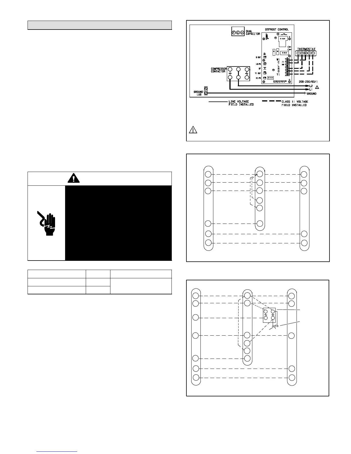
Figure 29. Typical Field Wiring
THERMOSTAT INDOOR UNIT OUTDOOR UNIT
R
C
W1
Y1
O
G
R
C
W1
W2
W3
G
R
C
W1
Y1
O
COMMON
1ST-STAGE
AUXILIARY
HEAT
INDOOR BLOWER
COMPRESSOR
24V POWER
REVERSING VALVE
COMMON
1ST-STAGE
AUXILIARY
HEAT
24V POWER
(SOME CONNECTIONS MAY NOT APPLY. REFER
TO SPECIFIC THERMOSTAT AND INDOOR UNIT.)
Figure 30. Outdoor and Blower Unit Thermostat
Designations
R
C
W1
Y1
O
G
R
C
W1
W2
W3
G
E
R
C
W1
Y1
O
EMERGENCY
HEAT
EMERGENCY
HEAT RELAY
OUTDOOR
THERMOSTAT
THERMOSTAT
INDOOR UNIT OUTDOOR UNIT
COMMON
1ST-STAGE
AUXILIARY
HEAT
INDOOR BLOWER
COMPRESSOR
COMMON
1ST-STAGE
AUXILIARY
HEAT
24V POWER 24V POWER
(SOME CONNECTIONS MAY NOT APPLY. REFER TO
SPECIFIC THERMOSTAT AND INDOOR UNIT.)
REVERSING VALVE
Figure 31. Outdoor and Blower Unit Thermostat
Designations (with emergency heat)

 Loading...