Page 18
506270−01 05/09
Start−Up and Charging Procedures
IMPORTANT
If unit is equipped with a crankcase heater, it should
be energized 24 hours before unit start−up to
prevent compressor damage as a result of slugging.
1. Rotate fan to check for binding.
2. Inspect all factory− and field−installed wiring for loose
connections.
3. After evacuation is complete, open both the liquid and
vapor line service valves to release the refrigerant
charge contained in outdoor unit into the system.
4. Replace the stem caps and tighten to the value listed
in table 1.
5. Check voltage supply at the disconnect switch. The
voltage must be within the range listed on the unit’s
nameplate. If not, do not start the equipment until you
have consulted with the power company and the
voltage condition has been corrected.
6. Set the thermostat for a cooling demand. Turn on
power to the indoor indoor unit and close the outdoor
unit disconnect switch to start the unit.
7. Recheck voltage while the unit is running. Power must
be within range shown on the nameplate.
8. Check system for sufficient refrigerate by using the
procedures listed under Testing and Charging
System.
TESTING AND CHARGING SYSTEM
This system uses HFC−410A refrigerant which operates at
much higher pressures than HCFC−22. The pre−installed
liquid line filter drier is approved for use with HFC−410A
only. Do not replace it with components designed for use
with HCFC−22. This unit is NOT approved for use with coils
which use capillary tubes as a refrigerant metering device.
SETTING UP TO CHECK CHARGE
1. Close manifold gauge set valves. Connect the center
manifold hose to an upright cylinder of HFC−410A.
2. Connect the manifold gauge set to the unit’s service
ports as illustrated in figure 2.
low pressure gauge to vapor service port
high pressure gauge to liquid service port
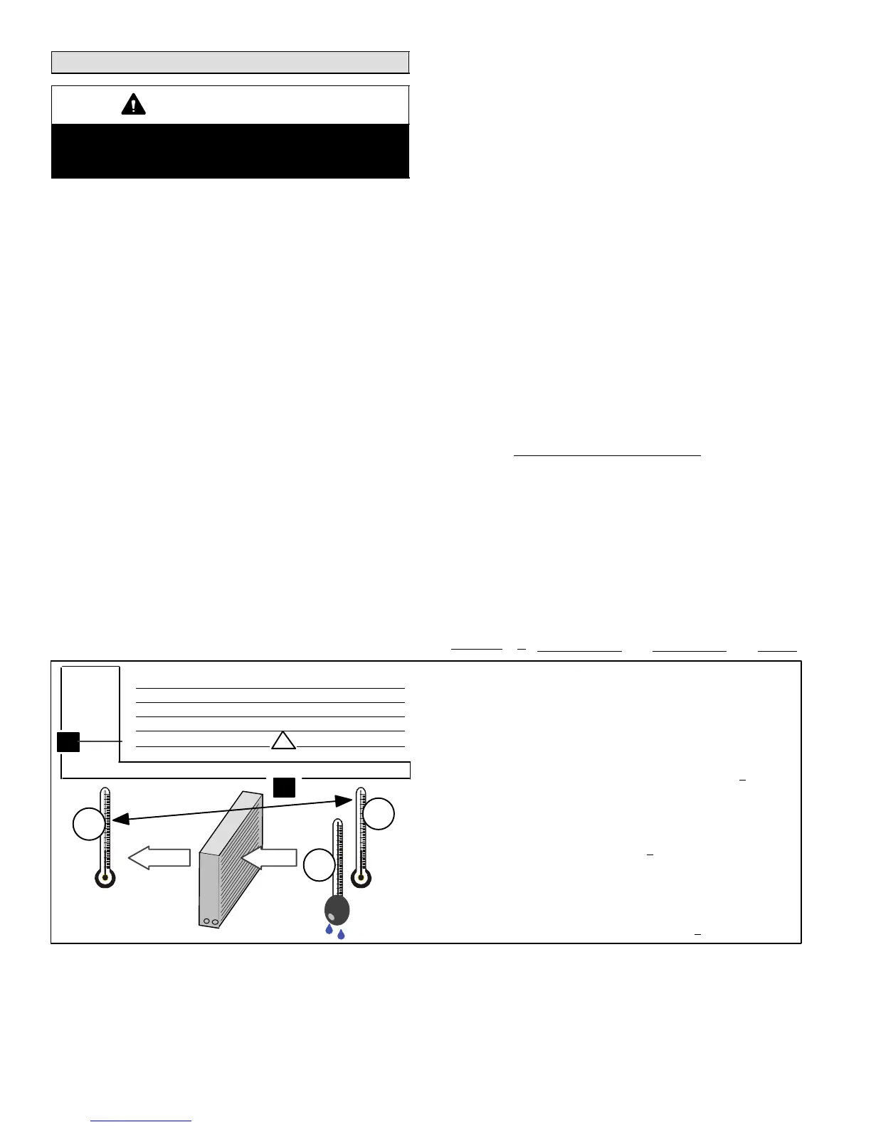
COOLING MODE INDOOR AIRFLOW CHECK
Check airflow using the Delta−T (DT) process using the
illustration in figure 32.
HEATING MODE INDOOR AIRFLOW CHECK
Blower airflow (CFM) may be calculated by energizing
electric heat and measuring:
Temperature rise between the return air and supply air
temperatures at the indoor coil blower unit,
Measuring voltage supplied to the unit,
Measuring amperage being drawn by the heat unit(s).
Then, apply the measurements taken in following formula
to determine CFM:
CFM =
Amps x Volts x 3.41
1.08 x Temperature rise (F)
CALCULATING CHARGE
If the system is void of refrigerant, first, locate and repair
any leaks and then weigh in the refrigerant charge into the
unit. To calculate the total refrigerant charge:
Amount
specified
on
nameplate
Adjust amount. for
variation in line set
length listed on table
in figure 33.
Additional charge
specified per
indoor unit
match−up listed in
table 3.
Total
charge
+ + =
1. Determine the desired DTMeasure entering air temperature
using dry bulb (A) and wet bulb (B). DT is the intersecting value of A
and B in the table (see triangle).
2. Find temperature drop across coilMeasure the coil’s dry bulb
entering and leaving air temperatures (A and C). Temperature Drop
Formula: (T
Drop
) = A minus C.
3. Determine if fan needs adjustmentIf the difference between
the measured T
Drop
and the desired DT (T
Drop
–DT) is within +3º, no
adjustment is needed. See examples: Assume DT = 15 and A temp.
= 72º, these C temperatures would necessitate stated actions:
Cº T
Drop
– DT = ºF ACTION
53º 19 – 15 = 4 Increase the airflow
58º 14 – 15 = −1 (within +3º range) no change
62º 10 – 15 = −5 Decrease the airflow
4. Adjust the fan speedSee indoor unit instructions to increase/
decrease fan speed.
Changing air flow affects all temperatures; recheck temperatures to
confirm that the temperature drop and DT are within +3º.
DT
80 24 24 24 23 23 22 22 22 20 19 18 17 16 15
78 23 23 23 22 22 21 21 20 19 18 17 16 15 14
76 22 22 22 21 21 20 19 19 18 17 16 15 14 13
74 21 21 21 20 19 19 18 17 16 16 15 14 13 12
72 20 20 19 18 17 17 16 15 15 14 13 12 11 10
70 19 19 18 18 17 17 16 15 15 14 13 12 11 10
57 58 59 60 61 62 63 64 65 66 67 68 69 70
Temp.
of air
entering
indoor
coil ºF
INDOOR
COIL
DRY
BULB
DRY
BULB
WET
BULB
B
T
Drop
19º
A
Dry−bulb
Wet−bulb ºF
A
72º
B
64º
C
53º
air flowair flow
All temperatures are
expressed in ºF
Figure 32. Checking Indoor Coil Airflow Guide

 Loading...