Page 23
XP13 SERIES
DEFROST CONTROL TIMING PINS
Each timing pin selection provides a different
accumulated compressor run time period for one defrost
cycle. This time period must occur before a defrost cycle
is initiated. The defrost interval can be adjusted to 30
(T1), 60 (T2), or 90 (T3) minutes (see figure 35). The
defrost timing jumper is factory−installed to provide a
60−minute defrost interval. If the timing selector jumper
is not in place, the control defaults to a 90−minute defrost
interval. The maximum defrost period is 14 minutes and
cannot be adjusted.
A TEST option is provided for troubleshooting. The TEST
mode may be started any time the unit is in the heating
mode and the defrost thermostat is closed or
jumpered. If the jumper is in the TEST position at
power-up, the control will ignore the test pins. When the
jumper is placed across the TEST pins for two seconds,
the control will enter the defrost mode. If the jumper is
removed before an additional 5−second period has
elapsed (7 seconds total), the unit will remain in defrost
mode until the defrost thermostat opens or 14 minutes
have passed. If the jumper is not removed until after the
additional 5−second period has elapsed, the defrost will
terminate and the test option will not function again until the
jumper is removed and re−applied.
COMPRESSOR DELAY
The defrost board has a field−selectable function to reduce
occasional sounds that may occur while the unit is cycling
in and out of the defrost mode. The compressor will be
cycled off for 30 seconds going in and out of the defrost
mode when the compressor delay jumper is removed.
NOTE − The 30-second compressor feature is ignored
when jumpering the TEST pins.
TIME DELAY
The timed-off delay is five minutes long. The delay helps to
protect the compressor from short-cycling in case the
power to the unit is interrupted or a pressure switch opens.
The delay is bypassed by placing the timer select jumper
across the TEST pins for 0.5 seconds.
PRESSURE SWITCH CIRCUIT
The defrost control incorporates two pressure switch
circuits. The high pressure switch (S4) is
factory-connected to the board’s HI PS terminals (see
figure 35). The board also includes a low pressure, or
loss-of-charge-pressure, switch (S87). Switches are
shown in wiring diagrams in figures 28 and 35.
During a single demand cycle, the defrost control will lock
out the unit after the fifth time that the circuit is interrupted
by any pressure switch wired to the control board. In
addition, the diagnostic LEDs will indicate a locked-out
pressure switch after the fifth occurrence of an open
pressure switch as listed in table 6. The unit will remain
locked out until power to the board is interrupted, then
re-established or until the jumper is applied to the TEST
pins for 0.5 seconds.
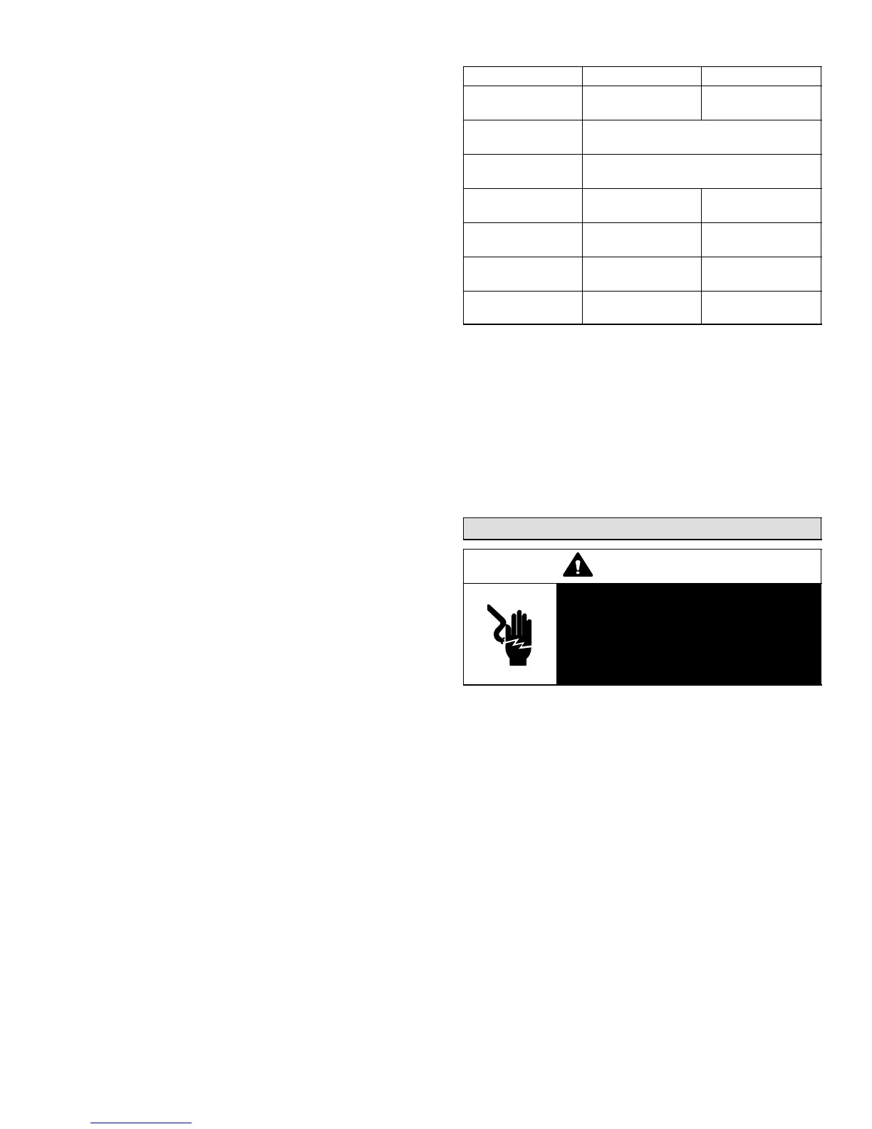
Table 6. Defrost Control Board Diagnostic LED
Mode Green LED (DS2) Red LED (DS1)
No power to con-
trol
OFF OFF
Normal operation /
power to control
Simultaneous Slow FLASH
Anti-short cycle
lockout
Alternating Slow FLASH
Low pressure
switch fault
OFF Slow FLASH
Low pressure
switch lockout
OFF ON
High pressure
switch fault
Slow FLASH OFF
High pressure
switch lockout
ON OFF
NOTE − The defrost control board ignores input from the
low-pressure switch terminals as follows:
S during the TEST mode,
S during the defrost cycle,
S during the 90-second start-up period,
S and for the first 90 seconds each time the reversing
valve switches heat/cool modes.
DIAGNOSTIC LEDS
The defrost board uses two LEDs for diagnostics. The
LEDs flash a specific sequence according to the condition.
Maintenance
WARNING
Electric shock hazard. Can cause
injury or death. Before attempting to
perform any service or maintenance,
turn the electrical power to unit OFF at
disconnect switch(es). Unit may have
multiple power supplies.
Before the start of each heating and cooling season, the
following service checks should be performed by a
qualified service technician. First, turn off electrical power
to the unit prior to performing unit maintenance.
Inspect and clean the outdoor and indoor coils. The
outdoor coil may be flushed with a water hose.
NOTE − It may be necessary to flush the outdoor coil
more frequently if it is exposed to substances which
are corrosive or which block airflow across the coil
(e.g., pet urine, cottonwood seeds, etc.)
Visually inspect the refrigerant lines and coils for leaks.
Check wiring for loose connections.
Check voltage at the indoor and outdoor units (with
units operating).
Check the amperage draw at the outdoor fan motor,
compressor, and indoor blower motor. Values should
be compared with those given on unit nameplate.
Check, clean (or replace) indoor unit filters.
Check the refrigerant charge and gauge the system
pressures.

 Loading...