Page 14
506270−01 05/09
and expose surface of the Teflon ring with refrigerant
oil.
5. Attach the liquid line assembly to the CTXV. Finger
tighten and use an appropriately sized wrench to turn
an additional 1/2 turn clockwise as illustrated in figure
23, or 20 ft−lb.
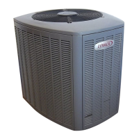
6. Attach the suction line sensing bulb in the proper
orientation as illustrated in figure 25 using the clamp
and screws provided.
NOTE − Insulating the sensing bulb once installed may be
required when the bulb location is external to the coil
casing.
ON 7/8" AND LARGER LINES,
MOUNT SENSING BULB AT
EITHER THE 4 OR 8 O’CLOCK
POSITION. NEVER MOUNT
ON BOTTOM OF LINE.
12
ON LINES SMALLER THAN
7/8", MOUNT SENSING BULB
AT EITHER THE 3 OR 9
O’CLOCK POSITION.
12
BULB
SUCTION LINE
SUCTION LINE
NOTE − NEVER MOUNT ON BOTTOM OF LINE.
BULB
BULB
BULB
Figure 25. TXV Sensing Bulb Installation
7. Remove and discard either the flare seal cap or flare
nut with copper flare seal bonnet from the equalizer
line port on the suction line as illustrated in figure 26.
IMPORTANT
When removing the flare nut, ensure that the copper
flare seal bonnet is removed.
SUCTION LINE
FLARE NUT
COPPER
FLARE SEAL
BONNET
MALE BRASS EQUALIZER
LINE FITTING
FLARE SEAL
CAP
OR
Figure 26. Copper Flare Seal Bonnet Removal
8. Connect the equalizer line from the TXV to the
equalizer suction port on the suction line. Finger
tighten the flare nut plus 1/8 turn (7 ft−lbs) as illustrated
in figure 23.
NOTE − To prevent any possibility of water damage,
properly insulate all parts of the TXV assembly that may
sweat due to temperature differences between the valve
and its surrounding ambient temperatures.
See the XP13 Engineering Handbook for approved CTXV
kit match−ups and application information.
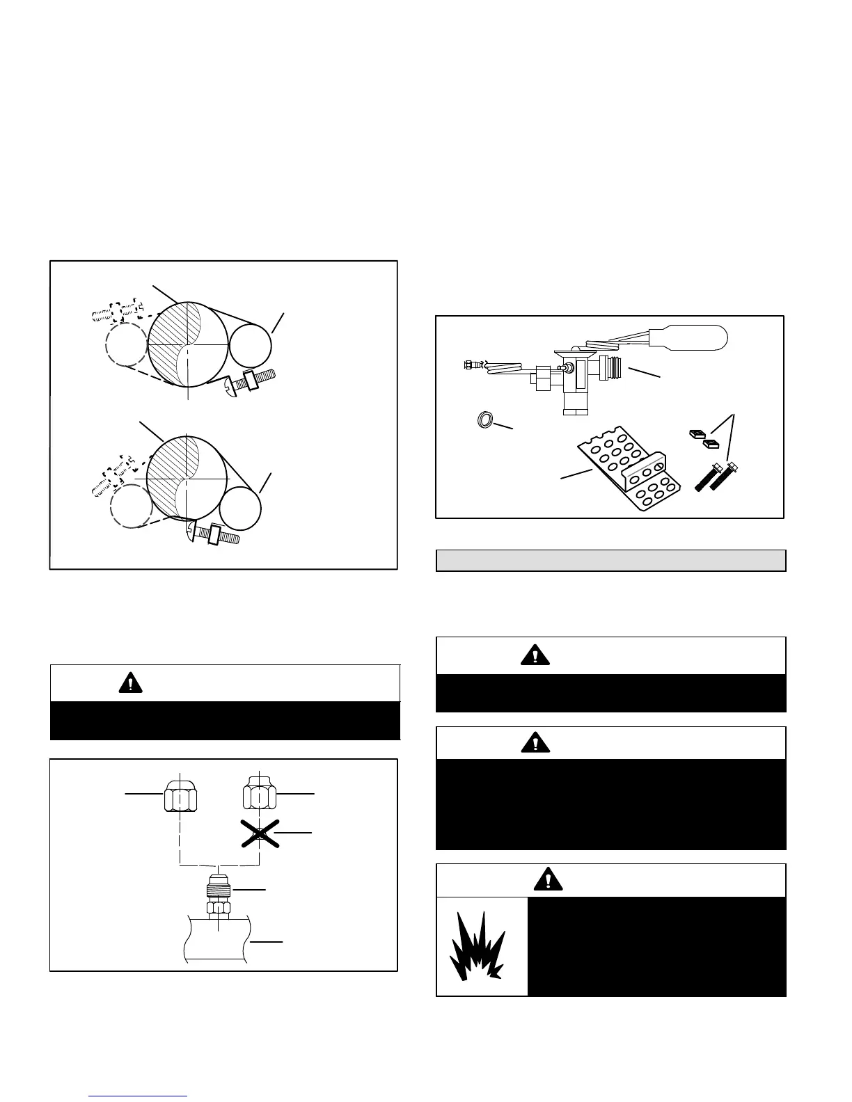
The reference CTXV kits include:
1 CTXV
2 Teflon rings
1 1 1/4" wide copper mounting strap for sensing bulb
2 #10 hex head bolts and nuts for securing sensing bulb
CTXV (1)
COPPER
MOUNTING
STRAP (1)
HEX HEAD BOLTS
AND NUTS (2)
TEFLON
RINGS (2)
Figure 27. CTXV Kit Components
Testing for Leaks
After the line set has been connected to the indoor unit and
air conditioner, check the line set connections and indoor
unit for leaks. Use the following procedure to test for leaks:
IMPORTANT
Leak detector must be capable of sensing HFC
refrigerant.
WARNING
Refrigerant can be harmful if it is inhaled.
Refrigerant must be used and recovered
responsibly.
Failure to follow this warning may result in personal
injury or death.
WARNING
When using a high pressure gas such
as dry nitrogen to pressurize a
refrigeration or air conditioning
system, use a regulator that can
control the pressure down to 1 or 2
psig (6.9 to 13.8 kPa).

 Loading...