Page 18 - IOM / ROOF-TOP FLEXY™ Series
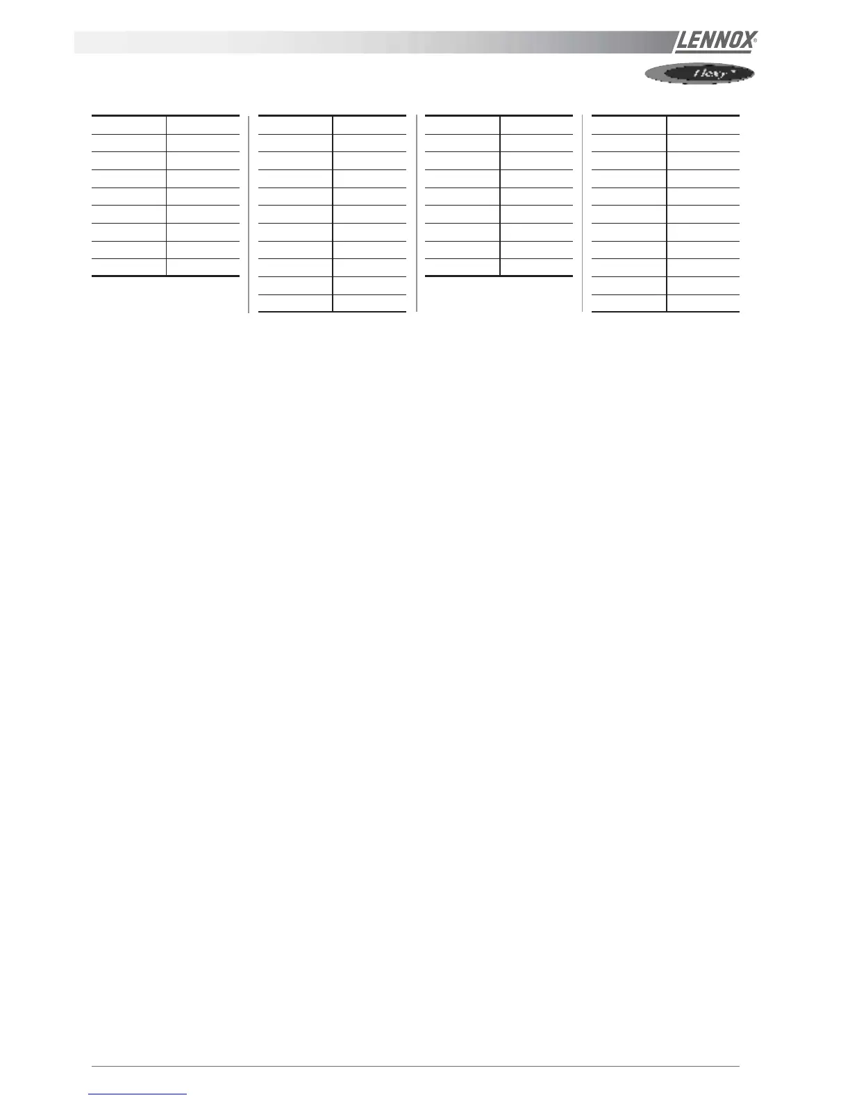
Configuration table LF20
COMMISSIONING
F.A050 11
F.A060 12
F.A070 13
F.A085 14
F.A100 15
F.A120 16
F.A140 17
F.A160 18
F.A190 19
FXA025 20
FXA030 21
FXA035 22
FXA040 23
FXA055 24
FXA070 25
FXA085 26
FXA100 27
FXA110 28
FXA140 29
FXA170 30
F.K050 111
F.K060 112
F.K070 113
F.K085 114
F.K100 115
F.K120 116
F.K140 117
F.K160 118
F.K190 119
FXK025 120
FXK030 121
FXK035 122
FXK040 123
FXK055 124
FXK070 125
FXK085 126
FXK100 127
FXK110 128
FXK140 129
FXK170 130
Switches on KP01
1 = on ....................... Option : pressure pick-up on air 500 pa (on FLEXY™ off = sensor 1000 pa)
2 = on | 3 = off ................... Option : hot water coil
2 = off | 3 = on ................... Option : electrical heater
2 = on | 3 = on ...................Option : gas burner
4 = on ....................... Option : cycle reversing valve, compressors (heat pump)
5 = on ....................... Option : heating of great power / or / pump (except freezing of the hot water coil)
6 = on ....................... Option : fresh air, economiser
7 = on ....................... Option : fresh air, all fresh air
8 = on ....................... Option : KP02 / KP17
POWERING THE UNIT
- Power up the unit by closing the isolator switch (if fitted).
- Close all circuit breakers and power up the unit, remove
the bridge on connector J14 if fitted.
- If now only one of the components rotates in the wrong
direction, disconnect the power supply at the machine's
isolator switch (if fitted) and reverse two of the
component's phases on the terminal within the electrical
panel.
- Check the current drawn against the rated values, in
particular on the supply fan.
- If the readings on the fan are outside the specified limits,
this usually indicates excessive air flow which will affect
the life expectancy and the thermodynamic performan-
ces of the unit. This will also increase the risks of water
ingress into the unit. Refer to the "air flow balancing"
section to correct the problem.
At this point attach the manometers to the refrigerant circuit.
RUN TEST
Start unit in cooling mode
Thermodynamic readings using manometers and prevailing
environmental conditions.
No rated values are given here. These depend on the
environmental conditions both outside and inside the building
during operation. However, an experienced refrigeration
engineer will be able to detect any abnormal machine
operation.
Safety test
- "Dirty filter" detection test : vary the set-point value in
respect to the air pressure value. Observe the response
of the CLIMATIC™.
- Same procedure for detecting "Missing filter" or "Air flow
detection".
- Check the smoke detection function (if fitted).
- Check the Firestat by pressing the test button(if fitted).
- Disconnect the circuit breakers of the outdoor fans and
check the high pressure cut-out points on different
refrigerant circuits.
Reverse cycle test
This test is designed to check the good operation of the 4-
way reversing valves on heat pump reversible systems. Start
the reverse cycle by adjusting the cold or hot temperature
threshold data according to the indoor and outdoor conditions
at the time of test.