Page 52 - IOM / ROOF-TOP FLEXY™ Series
GAS BURNERS
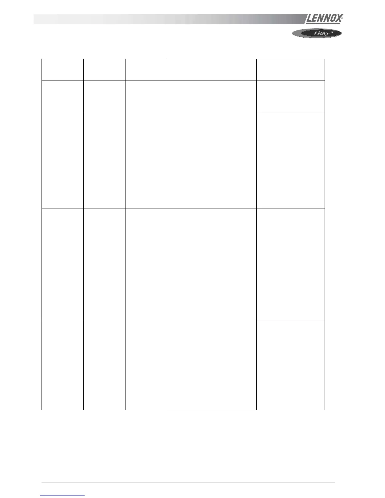
DIAGNOSTIC TABLE GAS BURNER
STAGES
NORMAL
OPERATION
FAULT ACTIONS SOLUTIONS
Heating
requested
Contactors
KM21-22
engaged
Contactors do
not engage
• Check safety thermostats B29-
30 in the air duct before the gas
heat exchanger
• Replace component
Contactors
KM21-22 are
engaged
Extraction fans
are running
Nothing
happens
• Check the free movement of the
fan wheel
• Check the supply temperature
limitation thermostats B45-46
• Check GAS low pressure
switches B17-18
• Check electrical connection on
the Honeywell control block
and on EF45-46 connection
boards
• Check the fan supply voltage
• Replace thermostat
• Open GAS Supply
• Replace EF 45-46 if
necessary
Extraction fan
ON
After 30
seconds: the
fire-up
electrode must
create sparks
Continuous
ventilation
without sparks
by electrode
• Check position of the fire-up
electrode (refer to preliminary
checks and verifications §1)
• Check the pressure drop at the
pressure switch : It must be
higher than 200 Pa
• Check the good operation of the
pressure switch using an
Ohmmeter and by sucking
through the tube to create a
depression.
• Check the operation the Backfire
thermostat B32-B33
• Re-position the
pressure taping
tube.(§5.d)
• Change the pressure
switch
• Reset or replace the
Thermostat
Continuous
ventilation with
sparks created
by electrode
After 2 seconds
the gas burner
fires-up
After 4 second
the GAS Burner
still not running
and Safety
shutdown by
the Honeywell
Block.
• Check injection pressure during
start-up (value for high heat)
• Check the supply voltage to the
control box (continuous voltage).
Refer to figure 61.
• Remove the control box from the
gas block. Check using an
ohmmeter the solenoid coil of
the GAS block (4 kOhm). Refer
to figure 62
• Remove the air from the
pipe-work
• Adjust the injection
pressure to high heat
value
• Change the control box
if the GAS valve is OK.
• Change the gas valve
control