Page 64 - IOM / ROOF-TOP FLEXY™ Series
USING THE KP02 MAINTENANCE CONTROL DISPLAY
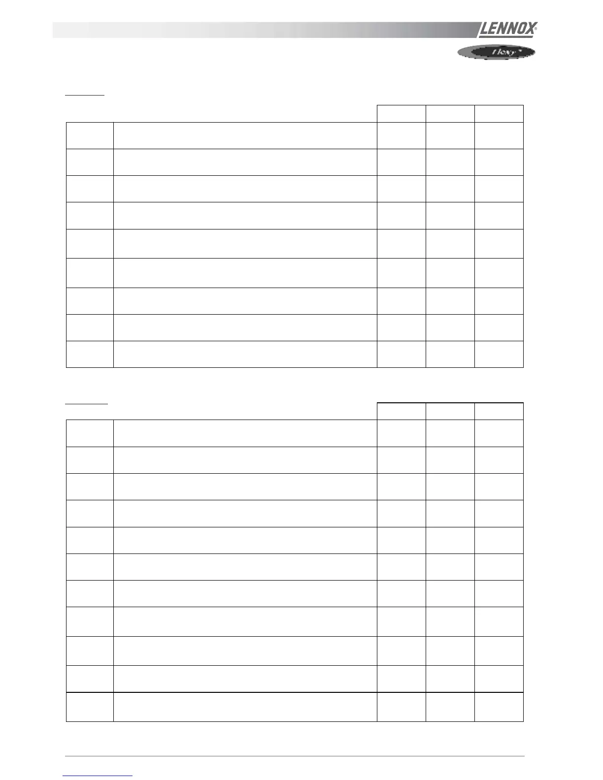
LIST OF SETPOINTS (LF 20 - APRIL 2002) - cont'd
1st Level
Mini. Factory Maxi.
C 041
[Safety limits] Room relative humidity low limit (in %) - Threshold of
activation of the safety cut-out
0 % 0 % 50 %
C 042
[Limit safety] Room absolute humidity low limit (in g/kg) - Threshold of
activation of the safety cut-out
0.0 g/kg 0.0 g/kg 30.0 g/kg
C 043
[Safety limits] Room relative humidity high limit (in %) - Threshold of
activation of the safety cut-out
50 % 100 % 100 %
C 044
[Limit safety] Room absolute humidity high limit (in g/kg) - Threshold
of activation of the safety cut-out
0.0 g/kg 30.0 g/kg 30.0 g/kg
C 045
[Anticipation function] Bottom of slope (in °c) - Limit of activation of
the function - This allows an anticipated start-up in the morning mode
depending on the outside temperature.
0.0 c 10.0 c 20.0 c
C 046
[Anticipation function] Slope - Number of minutes of anticipation per
degrees. This allows an anticipated start-up in the morning mode
depending on the outside temperature.
0 0 100
C 047
[Co²] Fresh air dampers opening threshold (in ppm)
0 ppm 1000 ppm 2000 ppm
C 048
[Co²] Fresh air dampers maximum opening limit (in ppm)
0 ppm 1500 ppm 2000 ppm
C 049
[Extraction] Threshold of activation of the power exhaust fan
according to the position of the economiser damper (in %)
0 % 10% 100 %
2nd Level
Mini. Factory Maxi.
C 050
[kp17] [Mode] Maximum limit for room temperature, Day mode (in °c)
- (active for the mode Day)
21.0 c 27.0 c 35.0 c
C 051
[kp17] [Mode] Minimum limit for room temperature, Day mode (in °c) -
(active for the mode Day)
8.0 c 17.0 c 21.0 c
C 052
[Room control] Minimum operation time for a stage (in seconds)
25 s 180 s 1800 s
C 053
[Room control] Temperature difference between the beginning and
the end of a stage of control in cooling. (in °c)
0.0 c 1.0 c 10.0 c
C 054
[Room regulation] Temperature difference between two stages of
control in cooling. (in °c)
0.1 c 1.0 c 10.0 c
C 055
[Room control] Temperature difference between the beginning and
the end of a stage of control in heating. (in °c)
0.0 c 0.5 c 10.0 c
C 056
[Room control] Temperature difference between two stages of control
in heating. (in °c)
0.1 c 0.5 c 10.0 c
C 057
[Room control] Choice of the priority for the control in heating.
[On] Hot water coil or electrical heater or gas then compressors
[Off]. Compressors then hot water coil or electrical heater or gas
Off Off On
C 058
[Supply control] Activation of the control. – The control of the supply
applies when the room temperature is in the dead zone. - This
function allows to maintain comfort with the supply air
Off Off On
C 059
[Supply control] Sampling time (in seconds)
1 s 10 s 120 s
C 060
[Supply control] Choice of the priority for the control in heating
[On] Hot water coil or electrical heater or gas then compressors
[Off] Compressors then hot water coil or electrical heater or gas
Off Off On
 Loading...