Page 58
IX− Troubleshooting
Two Stage Variable Speed Control Boards 18M99 & 49M59
UPON INITIAL POWER UP, REMOVE ALL THERMOSTAT DEMANDS TO THE UNIT
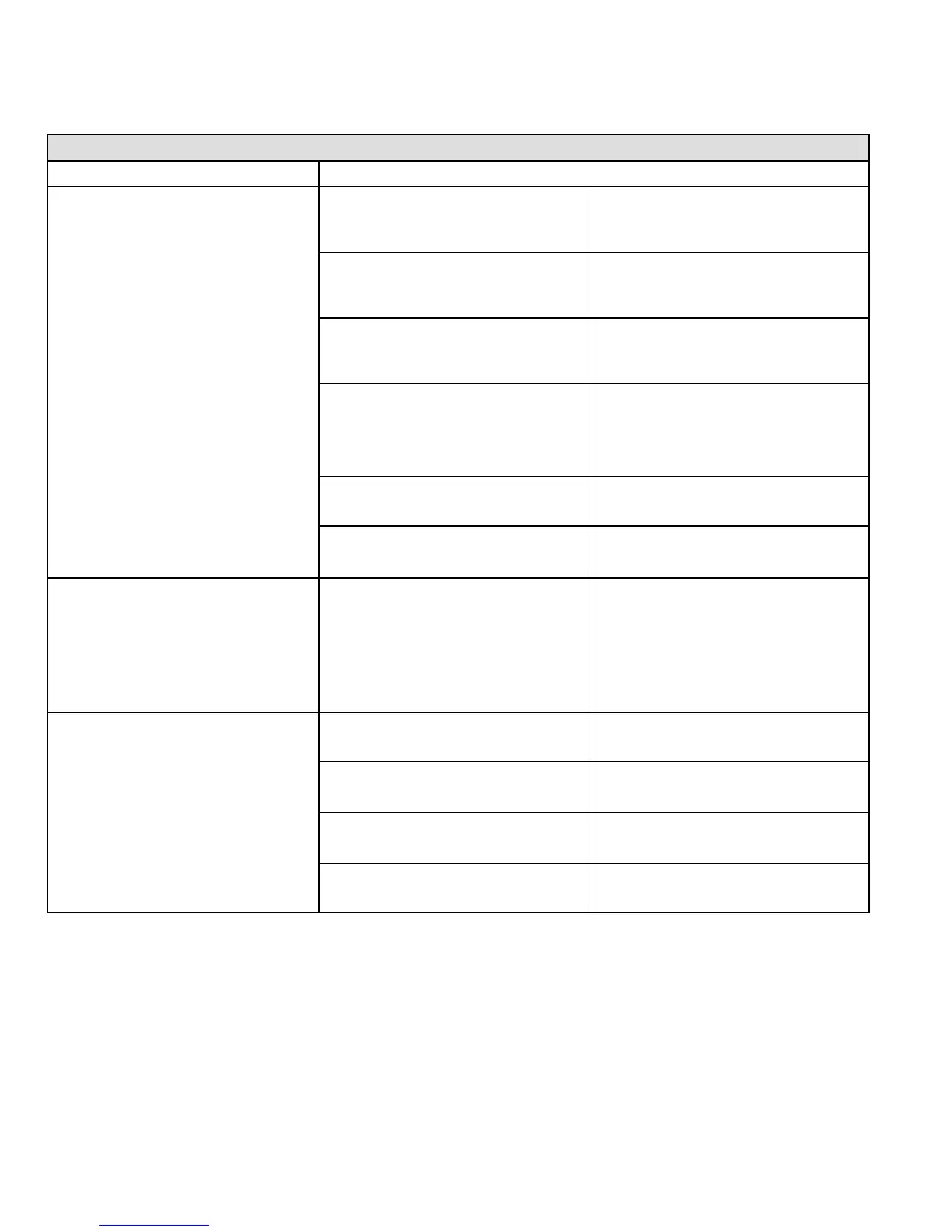
PROBLEM: 1 UNIT FAILS TO OPERATE IN THE COOLING, HEATING, OR CONTINUOUS FAN MODE
Condition Possible Cause Corrective Action / Comments
1.1
− Both diagnostic lights fail to light up.
LED#1−Off
LED#2−Off
1.1.1
Main voltage 120V not supplied to unit.
ACTION 1 − Check 120V main voltage.
Determine cause of main power failure.
1.1.2
Miswiring of furnace or improper con-
nections.
ACTION 1 − Check for correct wiring of 120V to
power make up box and transformer.
ACTION 2 − Check 24V wiring to control board.
1.1.3
Circuit breaker tripped or fails to
close.
ACTION 1 − Replace circuit breaker if it is reset
but does not have continuity.
ACTION 2 − If circuit breaker still trips, check for
short.
1.1.4
Door interlock switch failure.
ACTION 1 − Check that door switch is activated
when door is closed.
ACTION 2 − Check wire connections to switch, re-
place loose connectors.
ACTION 3 − Check continuity of switch in closed
position. Replace if defective.
1.1.5
Transformer Failure.
ACTION 1 − Check that transformer output is
24V. Replace if defective.
1.1.6
Failed control board.
ACTION 1 − If all the above items have been
checked, replace board.
1.2
− Diagnostic lights flash the reverse
polarity code.
LED#1−Fast Flash,
LED#2−Slow Flash.
1.2.1
120V main power polarity reversed.
ACTION 1 − Check the 120V has line and neutral
correctly input into control.
ACTION 2 − Reverse the line and neutral at the
120V field connection.
1.3
− Diagnostic lights flash the improper
main ground.
LED#1−Alternating Fast Flash
LED#2−Alternating Fast Flash
1.3.1
Improper ground to the unit.
ACTION 1 − Check that the unit is properly ground.
ACTION 2 − Install a proper main ground to the unit
1.3.2
Open ignitor circuit.
ACTION 1 − Check for correct wiring and loose
connections in the ignitor circuit. Check mult−plug
connections for correct installation.
1.3.3
Broken or failed ignitor.
ACTION 1 − Unplug ignitor and read resistance
across ignitor. If resistance does not read between
10.9 and 19.7 ohms, replace the ignitor.
1.3.4
Line voltage is below 75V.
ACTION 1 − Check that the line voltage is above
75V. Determine cause of voltage drop and supply
correct voltage to the control.
 Loading...


