Page 7
BLOWER DATA
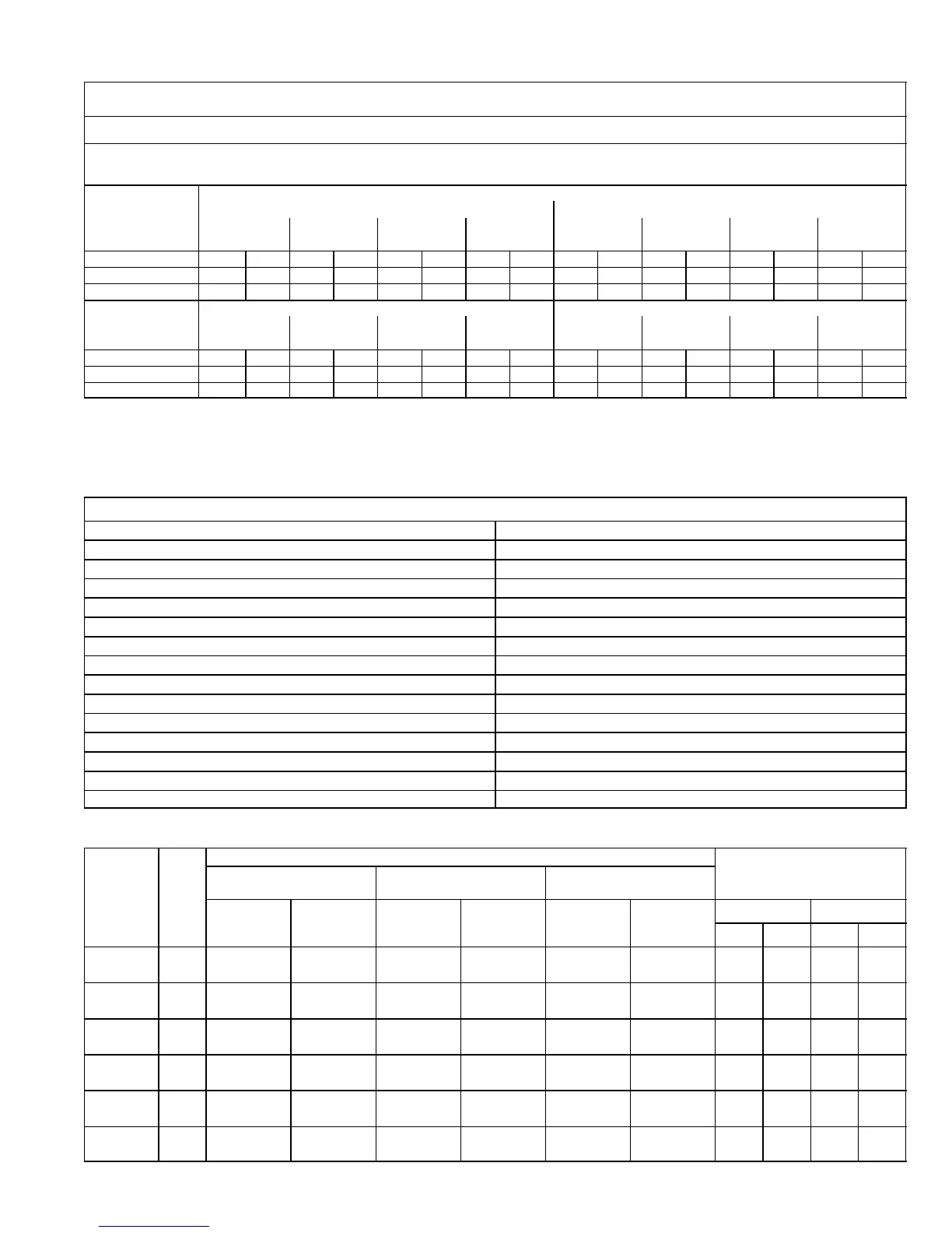
G60UHV−60D−135 BLOWER PERFORMANCE
0 through 0.80 in. w.g. (0 Through 200 Pa) External Static Pressure Range
Single Side Return Air − Air volumes in bold require field fabricated transition to accommodate 20 x 25 x 1 in. (508 x 635 x 25 mm) clean-
able air filter in order to maintain proper air velocity across the filter.
Blower Control Factory Settings ADJUST − NORM
HEAT − 2
COOL − 4
ADJUST"
Switch
Positions
Speed Switch Positions
2nd Stage HEAT" Speed 2nd Stage COOL" Speed
1 2 3 4 1 2 3 4
cfm L/s cfm L/s cfm L/s cfm L/s cfm L/s cfm L/s cfm L/s cfm L/s
+" (Plus) 1415 665 1625 765 1820 860 2015 950 1525 720 1650 780 1875 885 2095 990
NORM (Normal) 1285 605 1475 695 1655 780 1830 865 1385 655 1500 710 1705 805 1905 900
" (Minus) N/A N/A 1330 625 1490 705 1645 775 1245 590 1350 635 1535 725 1715 810
ADJUST"
Switch
Positions
1st Stage HEAT" Speed 1st Stage COOL" Speed
1 2 3 4 1 2 3 4
cfm L/s cfm L/s cfm L/s cfm L/s cfm L/s cfm L/s cfm L/s cfm L/s
+" (Plus) 1300 615 1480 700 1660 785 1850 875 965 455 1070 504 1215 573 1345 634
NORM (Normal) 1180 555 1345 635 1510 715 1680 795 885 417 975 460 1105 521 1225 578
" (Minus) N/A N/A 1210 570 1360 640 1510 715 795 375 870 410 995 469 1115 526
NOTES − The effect of static pressure and filter resistance is included in air volumes shown.
1st stage HEAT is approximately 91% of the same 2nd stage HEAT speed position.
1st stage COOL (two speed air conditioning units only) is approximately 70% (65% for units built prior to 09−2002) of the same 2nd stage COOL speed position.
Continuous Fan Only speed is approximately 38% of the same 2nd stage COOL speed position.
Lennox Harmony II zone control applications − Minimum blower heating speed is approximately 75% of the 1st stage HEAT speed position.
Lennox Harmony II zone control applications − Minimum blower cooling speed is approximately 45% of the 2nd stage COOL speed position.
N/A − 1st stage HEAT, speed position 1 with " (Minus) Adjust" setting, cannot be used with this model.
FILTER AIR RESISTANCE
cfm L/s in. w.g. Pa
0 0 0.00 0
200 95 0.01 0
400 190 0.03 5
600 285 0.04 10
800 380 0.06 15
1000 470 0.09 20
1200 565 0.12 30
1400 660 0.15 35
1600 755 0.19 45
1800 850 0.23 55
2000 945 0.27 65
2200 1040 0.33 80
2400 1130 0.38 95
2600 1225 0.44 110
HIGH ALTITUDE
Model
Input
Size
Gas
Altitude
Manifold Pressure
at all altitudes
0 − 4500 ft.
(0 − 1372 m)
4,501 − 7500 ft.
(1373 − 2286 m)
7501−10,000 ft.
(2286 − 3048 m)
Required
Conversion
Kit
Pressure
Switch
Required
Conversion
Kit
Pressure
Switch
Required
Conversion
Kit
Pressure
Switch
Low Fire High Fire
in. w.g. kPa in. w.g. kPa
070−1 to −6
Nat. N/A No Change N/A No Change 59M16 18M64 1.7 0.42 3.5 0.87
LPG 59M13 No Change 59M13 No Change 59M14 18M64 4.9 1.22 10.0 2.5
090−1 to −6
Nat. N/A No Change N/A 18M61 59M16 18M64 1.7 0.42 3.5 0.87
LPG 59M13 No Change 59M13 18M61 59M14 18M64 4.9 1.22 10.0 2.5
110/135−1 to
−6
Nat. N/A No Change N/A 18M63 59M16 18M61 1.7 0.42 3.5 0.87
LPG 59M13 No Change 59M13 18M63 59M14 18M61 4.9 1.22 10.0 2.5
070−7 and
later
Nat. N/A No Change N/A No Change 59M17 18M64 1.7 0.42 3.5 0.87
LPG 59M13 No Change 59M13 No Change 59M14 18M64 4.9 1.22 10.0 2.5
090−7 and
later
Nat. N/A No Change N/A 18M61 59M17 18M64 1.7 0.42 3.5 0.87
LPG 59M13 No Change 59M13 18M61 59M14 18M64 4.9 1.22 10.0 2.5
110/135−7
and later
Nat. N/A No Change N/A 18M63 59M17 18M61 1.7 0.42 3.5 0.87
LPG 59M13 No Change 59M13 18M63 59M14 18M61 4.9 1.22 10.0 2.5
Pressure switch is factory set. No adjustment necessary. All models use the factory installed pressure switch from 0−4500 feet (0−1370 m).
 Loading...


