Page 4
BLOWER DATA
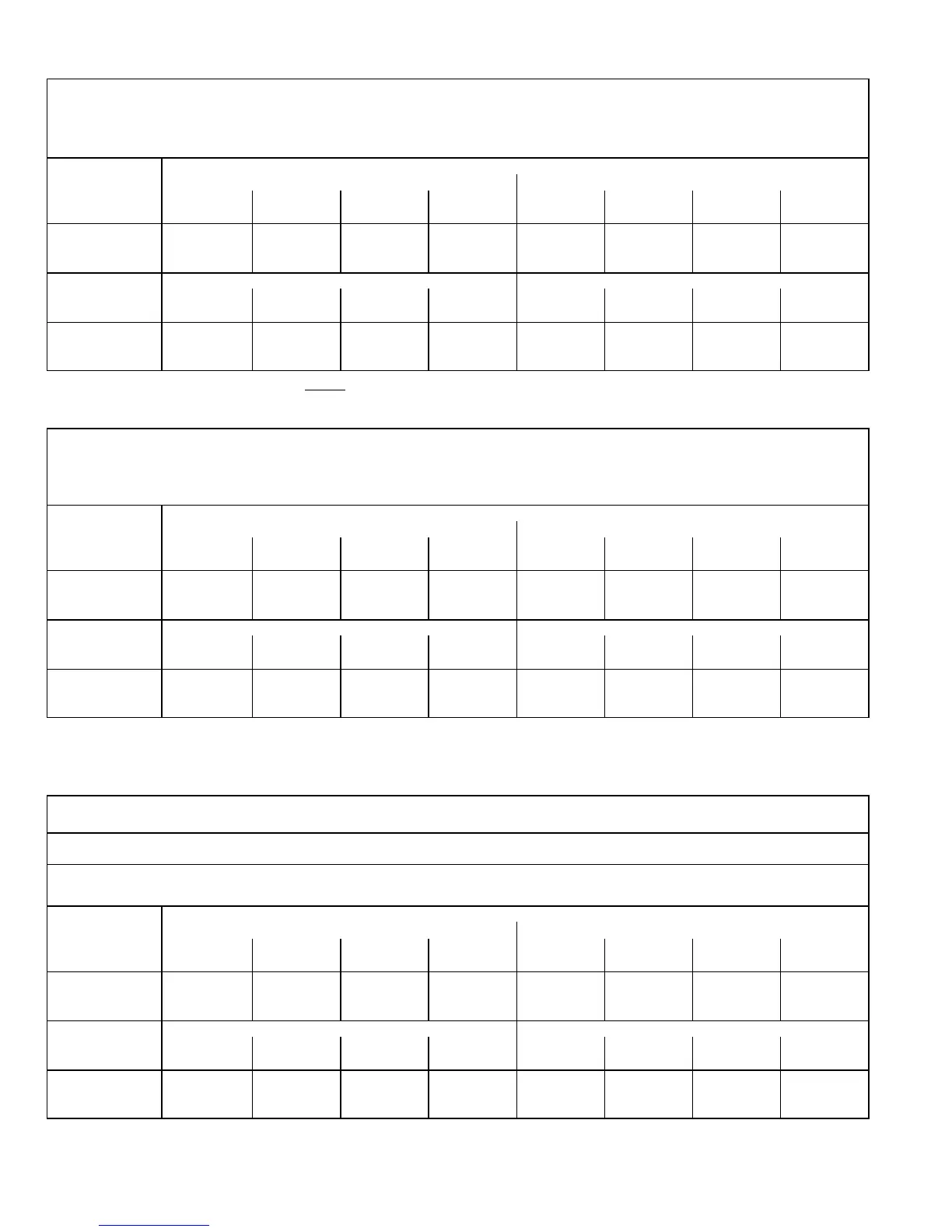
G60UHV−36A−070 BLOWER PERFORMANCE
0 through 0.80 in. w.g. (0 Through 200 Pa) External Static Pressure Range
Blower Control Factory Settings ADJUST − NORM
HEAT − 2
COOL − 4
ADJUST"
Switch
Positions
Speed Switch Positions
2nd Stage HEAT" Speed 2nd Stage COOL" Speed
1 2 3 4 1 2 3 4
cfm L/s cfm L/s cfm L/s cfm L/s cfm L/s cfm L/s cfm L/s cfm L/s
+" (Plus) 910 430 1055 495 1305 615 1350 635 1045 495 1230 580 1315 620 1420 670
NORM (Normal) 830 390 940 445 1165 550 1215 575 945 445 1100 520 1190 560 1300 615
" (Minus) 745 350 845 400 1030 485 1070 505 850 400 975 460 1035 485 1130 535
ADJUST"
Switch
Positions
1st Stage HEAT" Speed 1st Stage COOL" Speed
1 2 3 4 1 2 3 4
cfm L/s cfm L/s cfm L/s cfm L/s cfm L/s cfm L/s cfm L/s cfm L/s
+" (Plus) 840 395 965 455 1195 565 1235 585 730 344 800 377 860 405 994 469
NORM (Normal) 765 360 865 410 1055 495 1105 520 680 320 745 351 780 368 850 401
" (Minus) 700 330 785 370 955 450 985 465 620 292 685 323 725 342 760 358
NOTES − The effect of static pressure and filter resistance is included in air volumes shown.
1st stage HEAT is approximately 91% of the same 2nd stage
HEAT speed position.
1st stage COOL (two speed air conditioning units only) is approximately 70% (65% for units built prior to 09−2002) of the same 2nd stage COOL speed position.
Continuous Fan Only speed is approximately 38% of the same 2nd stage COOL speed position − minimum 500 cfm (235 L/s).
Lennox Harmony II zone control applications − Minimum blower heating speed is approximately 75% of the 1st stage HEAT speed position.
Lennox Harmony II zone control applications − Minimum blower cooling speed is approximately 45% of the 2nd stage COOL speed position.
G60UHV−36B−090 BLOWER PERFORMANCE
0 through 0.80 in. w.g. (0 Through 200 Pa) External Static Pressure Range
Blower Control Factory Settings ADJUST − NORM
HEAT − 2
COOL − 4
ADJUST"
Switch
Positions
Speed Switch Positions
2nd Stage HEAT" Speed 2nd Stage COOL" Speed
1 2 3 4 1 2 3 4
cfm L/s cfm L/s cfm L/s cfm L/s cfm L/s cfm L/s cfm L/s cfm L/s
+" (Plus) N/A N/A 1035 490 1280 605 1335 630 1010 475 1175 555 1275 600 1400 660
NORM (Normal) N/A N/A 930 440 1150 540 1190 560 935 440 1055 495 1130 535 1250 590
" (Minus) N/A N/A 830 390 1020 480 1050 495 830 390 940 445 1005 475 1090 515
ADJUST"
Switch
Positions
1st Stage HEAT" Speed 1st Stage COOL" Speed
1 2 3 4 1 2 3 4
cfm L/s cfm L/s cfm L/s cfm L/s cfm L/s cfm L/s cfm L/s cfm L/s
+" (Plus) N/A N/A 935 440 1150 540 1195 565 740 349 800 377 850 401 910 429
NORM (Normal) N/A N/A 840 395 1035 490 1070 505 675 318 740 349 780 368 845 398
" (Minus) N/A N/A 755 355 930 440 965 455 615 290 690 325 715 337 750 353
NOTES − The effect of static pressure and filter resistance is included in air volumes shown.
1st stage HEAT is approximately 91% of the same 2nd stage HEAT speed position.
1st stage COOL (two speed air conditioning units only) is approximately 70% (65% for units built prior to 09−2002) of the same 2nd stage COOL speed position.
Continuous Fan Only speed is approximately 38% of the same 2nd stage COOL speed position − minimum 500 cfm (235 L/s).
Lennox Harmony II zone control applications − Minimum blower heating speed is approximately 75% of the 1st stage HEAT speed position.
Lennox Harmony II zone control applications − Minimum blower cooling speed is approximately 45% of the 2nd stage COOL speed position.
N/A − 1st stage HEAT, speed position 1, cannot be used with this model.
G60UHV−60C−090 BLOWER PERFORMANCE
0 through 0.80 in. w.g. (0 Through 200 Pa) External Static Pressure Range
Bottom Return Air, Side Return Air with Optional RAB Return Air Base, Return Air from Both Sides or
Return Air from Bottom and One Side.
Blower Control Factory Settings ADJUST − NORM
HEAT − 2
COOL − 4
ADJUST"
Switch
Positions
Speed Switch Positions
2nd Stage HEAT" Speed 2nd Stage COOL" Speed
1 2 3 4 1 2 3 4
cfm L/s cfm L/s cfm L/s cfm L/s cfm L/s cfm L/s cfm L/s cfm L/s
+" (Plus) 1525 720 1715 810 1935 915 2125 1005 1630 770 1760 830 1960 925 2185 1030
NORM (Normal) 1385 655 1560 735 1760 830 1930 910 1480 700 1600 755 1785 840 1985 935
" (Minus) 1245 590 1400 660 1580 745 1740 820 1335 630 1440 680 1605 755 1785 845
ADJUST"
Switch
Positions
1st Stage HEAT" Speed 1st Stage COOL" Speed
1 2 3 4 1 2 3 4
cfm L/s cfm L/s cfm L/s cfm L/s cfm L/s cfm L/s cfm L/s cfm L/s
+" (Plus) 1395 660 1580 745 1780 840 1960 925 1120 528 1200 566 1370 646 1550 731
NORM (Normal) 1265 595 1440 680 1615 760 1780 840 1000 471 1100 519 1250 589 1375 648
" (Minus) 1140 540 1295 610 1465 690 1605 755 900 424 975 460 1120 528 1230 580
NOTES − The effect of static pressure and filter resistance is included in air volumes shown.
1st stage HEAT is approximately 91% of the same 2nd stage HEAT speed position.
1st stage COOL (two speed air conditioning units only) is approximately 70% (60% for units built prior to 09−2002) of the same 2nd stage COOL speed position.
Continuous Fan Only speed is approximately 38% of the same 2nd stage COOL speed position.
Lennox Harmony II zone control applications − Minimum blower heating speed is approximately 75% of the 1st stage HEAT speed position.
Lennox Harmony II zone control applications − Minimum blower cooling speed is approximately 42% of the 2nd stage COOL speed position.
 Loading...


