Page 9
I−UNIT COMPONENTS
G60UHV(X) unit components are shown in figure 1. The
gas valve, combustion air inducer and burners can be ac-
cessed by removing the burner access panel. Electrical
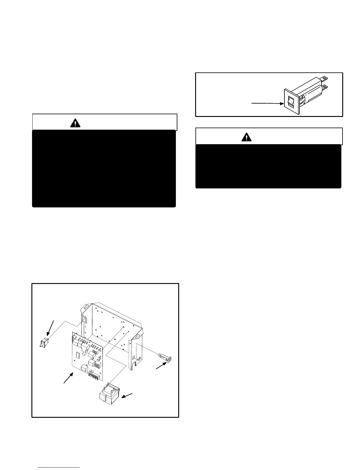
components are in the control box (figure 2) found in the
blower section.
G60UHV(X) units are factory equipped with a bottom return
air panel in place. The panel is designed to be field removed
as required for bottom air return. Markings are provided for
side return air and may be cut out in the field.
CAUTION
Electrostatic discharge can affect electronic
components. Take precautions during furnace
installation and service to protect the furnace’s
electronic controls. Precautions will help to
avoid control exposure to electrostatic dis-
charge by putting the furnace, the control and
the technician at the same electrostatic poten-
tial. Neutralize electrostatic charge by touching
hand and all tools on an unpainted unit surface,
such as the gas valve or blower deck, before per-
forming any service procedure.
ELECTROSTATIC DISCHARGE (ESD)
Precautions and Procedures
1. Control Transformer (T1)
A transformer located in the control box provides power to
the low voltage section of the unit. Transformers on all
models are rated 40VA with a 120V primary and a 24V sec-
ondary.
2. Door Interlock Switch (S51)
A door interlock switch rated 14A at 125VAC is wired in se-
ries with line voltage. When the blower door is removed the
unit will shut down.
FIGURE 2
CONTROL BOX G60UHV(X)
SureLight
CONTROL
BOARD
TRANSFORMER
CIRCUIT BREAKER
DOOR INTERLOCK
SWITCH
3. Circuit Breaker (CB8)
A 24V circuit breaker is also located in the control box.
The switch provides overcurrent protection to the trans-
former (T1). The breaker is rated 3A at 32V. If the current
exceeds this limit the breaker will trip and all unit opera-
tion will shutdown. The breaker can be manually reset
by pressing the button on the face. See figure 3.
FIGURE 3
CIRCUIT BREAKER CB8
PRESS TO RESET
WARNING
Shock hazard.
Disconnect power before servicing. Integrated
Control Board is not field repairable. If control is
inoperable, simply replace entire control.
Can cause injury or death. Unsafe operation will
result if repair is attempted.
4. Integrated Control Board(A92)
Boards 18M99 and 49M59
All G60UHV units are equipped with the Lennox two−
stage, variable speed integrated SureLight control board.
The system consists of a ignition / blower control board
(figure 4 with control terminal designations in tables 1
through 4) and ignitor (figure 12). The board and ignitor
work in combination to ensure furnace ignition and ignitor
durability. The SureLight integrated board controls all ma-
jor furnace operations. The board features two LED lights,
DS1 and DS2 for troubleshooting and four LED lights
(DS3, DS6, DS7 and DS8) to show furnace status. The
board also has two accessory terminals rated at (1) one
amp each. See table 5 for status code and table 6 for trou-
bleshooting diagnostic codes.
Electronic Ignition
At the beginning of the heat cycle the SureLight control
monitors the first stage and second stage combustion air
inducer prove switch. The control will not begin the heating
cycle if the first stage prove switch is closed (by−passed).
Likewise the control will not begin the second stage heating
cycle if the second stage prove switch is closed, and will re-
main in first stage heat. However, if the second stage prove
switch closes during the first stage heat pre−purge, the con-
trol will allow second stage heat. Once the first stage prove
switch is determined to be open, the combustion air induc-
er is energized on low (first stage) heat speed. When the
differential in the prove switch is great enough, the prove
switch closes and a 15−second pre−purge begins. If the
switch is not proven within 2−1/2 minutes, the control goes
into Watchguard−Pressure Switch mode for a 5−minute re−
set period.
 Loading...


