Page 12
C−Heating Components
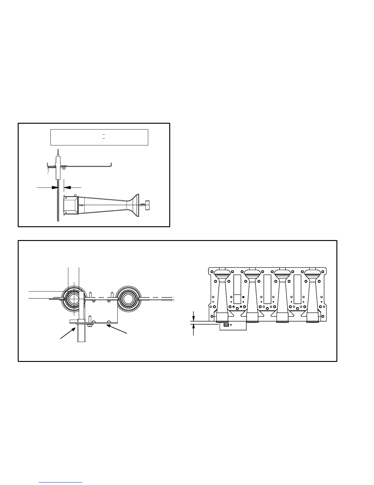
3. Flame Sensor
A flame sensor is located on the left side of the burner sup-
port. See figure 6. The sensor is mounted through the bot-
tom of the burner box and the tip protrudes into the flame
envelope of the left−most burner. The sensor can be re-
moved for service without removing any part of the burn-
ers. During operation, flame is sensed by current passed
through the flame and sensing electrode. The SureLight
control allows the gas valve to remain open as long as
flame signal is sensed.
FIGURE 6
NORMAL FLAME SIGNAL > 0.23 MICROAMPS
LOW FLAME SIGNAL < 0.22 MICROAMPS
DROP OUT SIGNAL = 0.16 MICROAMPS
5/16"
4. Ignitor
The SureLight ignitor is made of durable silicon nitride. Ig-
nitor longevity is enhanced by controlling voltage to the ig-
nitor. The board finds the lowest ignitor temperature which
will successfully light the burner, thus increasing the life of
the ignitor. Due to this feature of the board, voltage cannot
be measured so ignitor must be ohmed. Ohme value
should be 10.9 to 19.7. See 7 for ignitor location.
NOTE − The G61MP furnace contains electronic com-
ponents that are polarity sensitive. Make sure that the
furnace is wired correctly and is properly grounded.
5. Burners (Figure 7)
All units use inshot burners. Burners are factory set and do not
require adjustment. The manifold brackets are slotted so burn-
ers can be removed as an assembly for service. Burner main-
tenance and service is detailed in the MAINTENANCE sec-
tion of this manual. Each burner uses an orifice which is pre-
cisely matched to the burner input and is threaded into the
burner manifold. All G61MP natural gas units are fitted with
.089" sized orifices. See SPECIFICATIONS" tables for LP
kits and high altitude.
A flame retention ring in the end of each burner maintains cor-
rect flame length and shape and keeps the flame from lifting off
the burner head. In addition, the burner entrance to each clam-
shell is fitted with a corbel cup (orifice) used to direct the flow
of combustion products.
FIGURE 7
5/16"
13/32’
5/8"
SureLight Ignitor Location
BURNERS TOP VIEWBURNERS FRONT VIEW
MEASUREMENT IS TO I.D.
OF RETENTION RING
IGNITOR
BRACKET

 Loading...


