Page 35
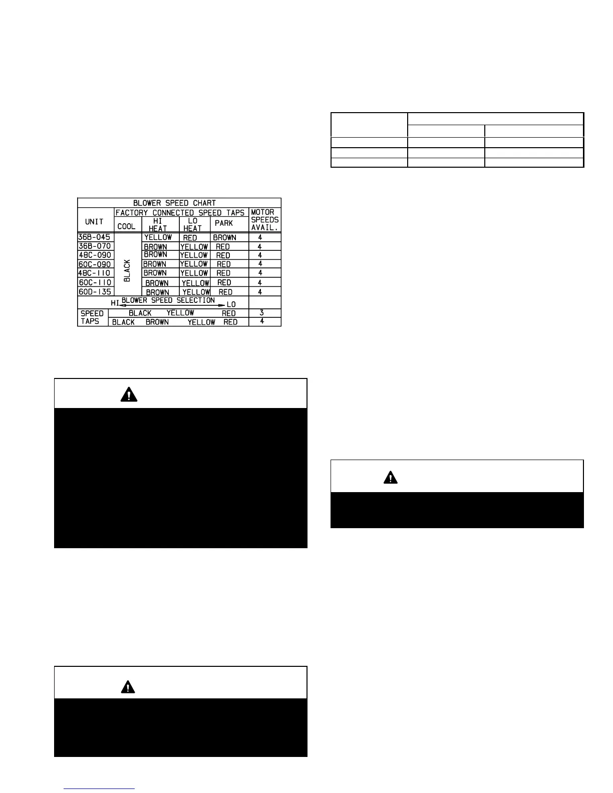
D−Blower Speed Taps
Blower speed tap changes are made on the SureLight con-
trol board. See figure 4. The unused tap must be secured
on dummy terminals "PARK " on the SureLight board. The
high heating tap is connected to the "HI HEAT " terminal
and the low heating / continuous blower tap is connected to
the "LO HEAT" terminal. The cooling tap is connected to the
COOL" tap.
To change existing heat tap, turn off power then switch out
speed tap on "HI HEAT" or LO HEAT" with tap connected
to "PARK ". See table 20 for blower motor tap colors for
each speed.
TABLE 20
VI−MAINTENANCE
WARNING
ELECTRICAL SHOCK, FIRE,
OR EXPLOSION HAZARD.
Failure to follow safety warnings exactly could result
in dangerous operation, serious injury, death or
property damage.
Improper servicing could result in dangerous opera-
tion, serious injury, death, or property damage.
Before servicing, disconnect all electrical power to
furnace.
When servicing controls, label all wires prior to dis-
connecting. Take care to reconnect wires correctly.
Verify proper operation after servicing.
At the beginning of each heating season, system should be
checked as follows by a qualified service technician:
Blower
Check the blower wheel for debris and clean if necessary.
The blower motors are prelubricated for extended bearing
life. No further lubrication is needed.
WARNING
The blower access panel must be securely in place
when the blower and burners are operating. Gas
fumes, which could contain carbon monoxide, can
be drawn into living space resulting in personal inju-
ry or death.
Filters
Filters should be inspected monthly. Clean or replace the
filters when necessary to ensure proper furnace opera-
tion. Replacement filters must be rated for high velocity
airflow. Table 21 lists recommended filter sizes.
TABLE 21
Furnace
Filter Size
Cabinet Size
Side Return Bottom Return
17−1/2" 16 X 25 X 1 (1) 16 X 25 X 1 (1)
21" 16 X 25 X 1 (1) 20 X 25 X 1 (1)
24−1/2" 16 X 25 X 1 (2) 24 X 25 X 1 (1)
Exhaust and air intake pipes
Check the exhaust and air intake pipes and all connections
for tightness and to make sure there is no blockage.
Electrical
1 − Check all wiring for loose connections.
2 − Check for the correct voltage at the furnace (furnace
operating).
3 − Check amp−draw on the blower motor.
Motor Nameplate__________Actual__________
Winterizing and Condensate Trap Care
1 − Turn off power to the unit.
2 − Have a shallow pan ready to empty condensate water.
3 − Remove the drain plug from the condensate trap and
empty water. Inspect the trap then reinstall the drain
plug.
Cleaning Heat Exchanger
If cleaning the heat exchanger becomes necessary, follow
the below procedures and refer to figure 1 when disassem-
bling unit. Use papers or protective covering in front of fur-
nace while removing heat exchanger assembly.
IMPORTANT
Safety glasses and surgical mask should be worn
when cleaning heat exchanger and or burner
assembly.
1 − Turn off electrical and gas supplies to the furnace.
2 − Remove the upper and lower furnace access panels.
3 − Mark all gas valve wires and disconnect them from
valve.
4 − Remove gas supply line connected to gas valve. Re-
move gas valve/manifold assembly.
5 − Remove sensor wire from sensor. Disconnect 2-pin
plug from the ignitor.
6 − Disconnect wires from flame roll−out switches.
7 − Remove burner box cover and remove four burner box
screws at the vestibule panel and remove burner box.
Set burner box assembly aside. G61MP−135 only −
Remove and discard two additional shipping screws.
See figure 41.
NOTE − If necessary, clean burners at this time. Follow
procedures outlined in Burner Cleaning section.
8 − Loosen three clamps and remove flexible exhaust tee.

 Loading...


