Page 18
Use the following steps to correctly size vent pipe diameter.
1 − Determine the vent termination and its corresponding
equivalent feet value according to table 11.
2 − Determine the number of 90° elbows required for both
indoor and outdoor (e.g. snow riser) use. Calculate the
corresponding equivalent feet of vent pipe.
3 − Determine the number of 45° elbows required for both
indoor and outdoor use. Calculate the corresponding
equivalent feet of vent pipe.
4 − Determine the length of straight pipe required.
5 − Add the total equivalent feet calculated in steps 1
through 4 and compare that length to the maximum
values given in table 12 for the proposed vent pipe di-
ameter. If the total equivalent length required exceeds
the maximum equivalent length listed in the appropri-
ate table, evaluate the next larger size pipe.
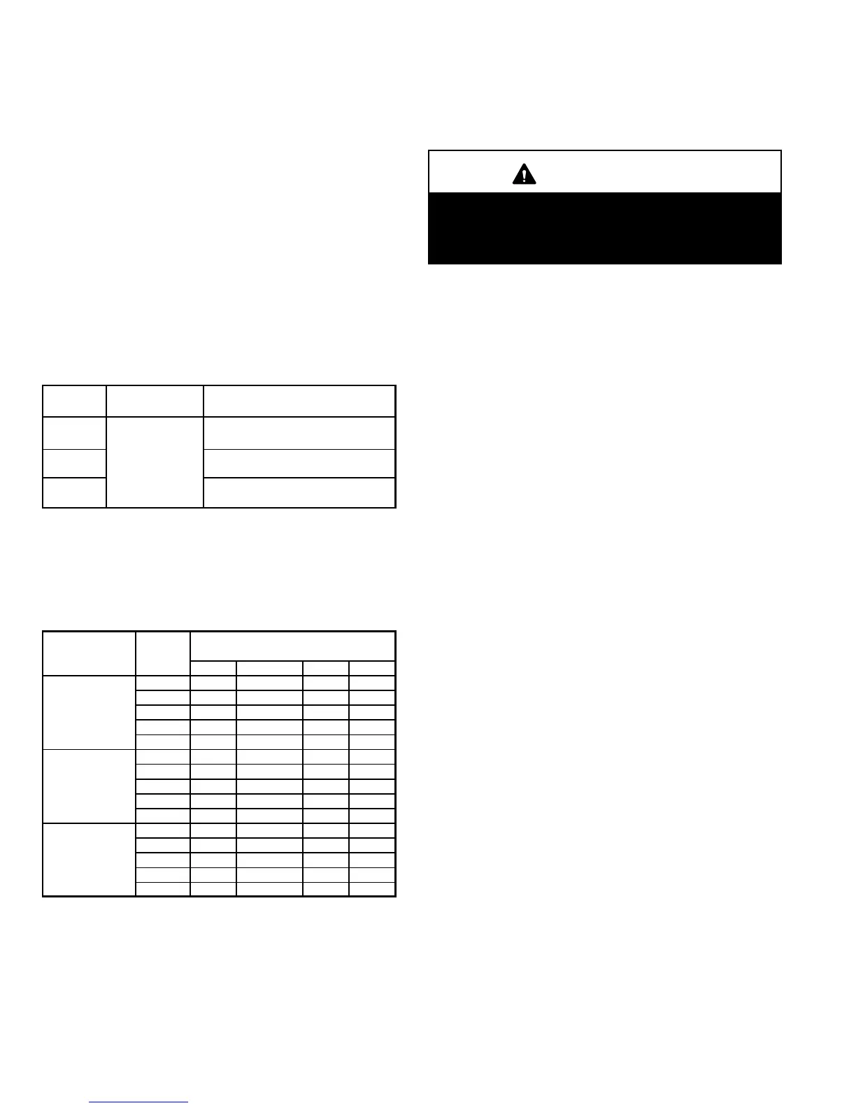
TABLE 12
MINIMUM VENT PIPE LENGTHS
G61MP
MODEL
MIN. EQUIV.
VENT LENGTH
EXAMPLE
045, 070,
090
5 ft. plus 2 elbows of 2", 2−1/2", 3"
or 4" diameter pipe
110**
15 ft.*
5 ft. plus 2 elbows of 2−1/2" 3" or 4"
diameter pipe
135***
5 ft. plus 2 elbows of 3" or 4"
diameter pipe
*Any approved termination may be added to the minimum equivalent length
listed.
**G61MP−48C−110 and G61MP−60C−110 must have 90° street ell (supplied)
installed directly into unit flue collar.
***G61MP−60D−135 must have 3" to 2" reducing ell (supplied) installed directly
into unit flue collar.
TABLE 13
MAXIMUM VENT PIPE LENGTHS
ALTITUDE
G61MP
MAXIMUM EQUIVALENT VENT
LENGTH FEET
2" dia. 2−1/2" dia. 3" dia. 4" dia.
045 59 65 77 234
070 59 65 78 214
0 − 4500
090 26 42 72 204
−
m
110* n/a 32 72 179
135** n/a n/a ***61 160
045 59 65 77 234
070 59 65 78 214
4501−7500
090 26 42 72 204
−
m
110* n/a 32 72 179
135** n/a n/a ***46 160
045 59 65 77 234
070 59 65 78 214
7501 − 10000
090 26 42 72 204
(2287 − 3048 m)
110* n/a 32 72 179
135** n/a n/a ***46 160
n/a −− Not allowed.
*G61MP−48C−110 and G61MP−60C−110 must have 90° street ell (supplied)
installed directly into unit flue collar.
**G61MP−60D−135 must have 3" to 2" reducing ell (supplied) installed directly
into unit flue collar.
***90° elbows used in configuration of G61MP−60D−135 vent, must be lim-
ited to 3" sweep elbows.
B−PVC Joint Cementing Procedure
All cementing of joints should be done according to the
specifications outlined in ASTM D 2855.
WARNING
DANGER OF EXPLOSION!
Fumes from PVC glue may ignite during system
check. Allow fumes to dissipate for at least 5 minutes
before placing unit into operation.
1 − Measure and cut vent pipe to desired length.
2 − Debur and chamfer end of pipe, removing any ridges
or rough edges. If end is not chamfered, edge of pipe
may remove cement from fitting socket and result in a
leaking joint.
3 − Clean and dry surfaces to be joined.
4 − Test fit joint and mark depth of fitting on outside of pipe.
5 − Uniformly apply liberal coat of PVC primer for PVC or
ABS cleaner for ABS to inside socket surface of fitting
and male end of pipe to depth of fitting socket.
6 − Promptly apply solvent cement to end of pipe and in-
side socket surface of fitting. Cement should be ap-
plied lightly but uniformly to inside of socket. Take
care to keep excess cement out of socket. Apply sec-
ond coat to end of pipe.
NOTE − Time is critical at this stage. Do not allow prim-
er to dry before applying cement.
7 − Immediately after applying last coat of cement to pipe,
and while both inside socket surface and end of pipe
are wet with cement, forcefully insert end of pipe into
socket until it bottoms out. Turn pipe 1/4 turn during as-
sembly (but not after pipe is fully inserted) to distribute
cement evenly.
NOTE − Assembly should be completed within 20 sec-
onds after last application of cement. Hammer blows
should not be used when inserting pipe.
8 − After assembly, wipe excess cement from pipe at end
of fitting socket. A properly made joint will show a
bead around its entire perimeter. Any gaps may indi-
cate a defective assembly due to insufficient solvent.
9 − Handle joints carefully until completely set.

 Loading...


