Page 15
12. Combustion Air Inducer (B6)
All G61MP units use a combustion air inducer to move air
through the burners and heat exchanger during heating
operation. The blower uses a PSC 120VAC motor. The
motor operates during all heating operation and is con-
trolled by the ignition control A3. Blower operates continu-
ously while there is a call for heat. The burner ignition con-
trol will not proceed with the ignition sequence until combus-
tion air inducer operation is sensed by the proving switches.
The CAI is installed on the cold end header box. The cold
end header box is a single piece made of hard plastic.
The box has an internal channel where the combustion
air inducer creates negative pressure at unit start up. The
channel contains an orifice used to regulate flow created
by the CAI. The box has pressure taps for the CAI prove
switch hoses.
The prove switches measure the pressures across the
CAI orifice or difference in the channel and the box. A
window is provided on the bottom right hand side of the
box to indicate orifice size. See figure 10. See table 7 for
orifice size per unit. If replacement is necessary the
gaskets used to seal the box to the vestbule panel
and the CAI to the box, must also be replaced.
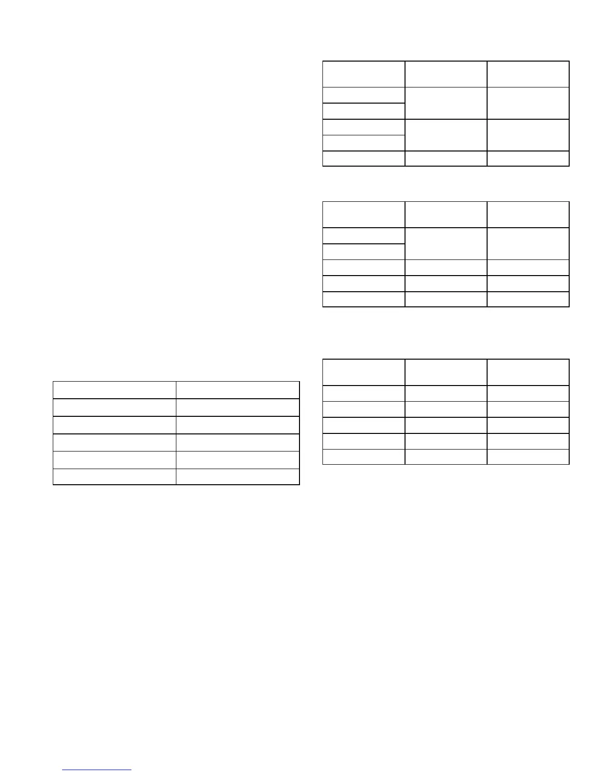
TABLE 7
G61MP Unit C.A.I. Orifice Size
−045 .719"
−070 .938"
−090 1.063"
−110 1.313"
−135 1.688"
TABLE 8
0’ to 4500’
G61MP Unit
Set Point
Second Stage
Set Point
First Stage
−045
"
"
−070
.
.
−090
"
"
−110
.
.
−135 0.60" 0.35"
TABLE 9*
4501’ to 7500’
G61MP Unit
Set Point
Second Stage
Set Point
First Stage
−045
"
"
−070
.
.
−090 0.75" 0.50"
−110 0.85" 0.50"
−135 0.55" 0.35"
*Unit may require conversion kit at this altitude. See High Altitude
table.
TABLE 10*
7501’ to 10,000’
G61MP Unit
Set Point
Second Stage
Set Point
First Stage
−045 0.95" 0.95"
−070 0.85" 0.85"
−090 0.60" 0.35"
−110 0.85" 0.50"
−135 0.55" 0.35"
*Unit may require conversion kit at this altitude. See High Altitude
table.

 Loading...


