Page 14
On heat demand (first or second stage) the switch senses
that the combustion air inducer is operating. It closes a cir-
cuit to the furnace control when pressure inside the cold
end header box decreases to a certain set point.
Set points vary depending on unit size. See tables 8, 9 and
10. The pressure sensed by the switch is negative. If the air
intake vent pipe or outlet vent pipe becomes obstructed
during operation, the switch senses a change of negative
pressure and opens the circuit to the furnace control and
gas valve. A bleed port on the switch allows relatively dry
air in the vestibule to purge switch tubing, to prevent con-
densate build up.
The switch is factory set and is not field adjustable. It is a
safety shut-down control in the furnace and must not be by−
passed for any reason. If switch is closed or by−passed, the
control will not initiate ignition at start up.
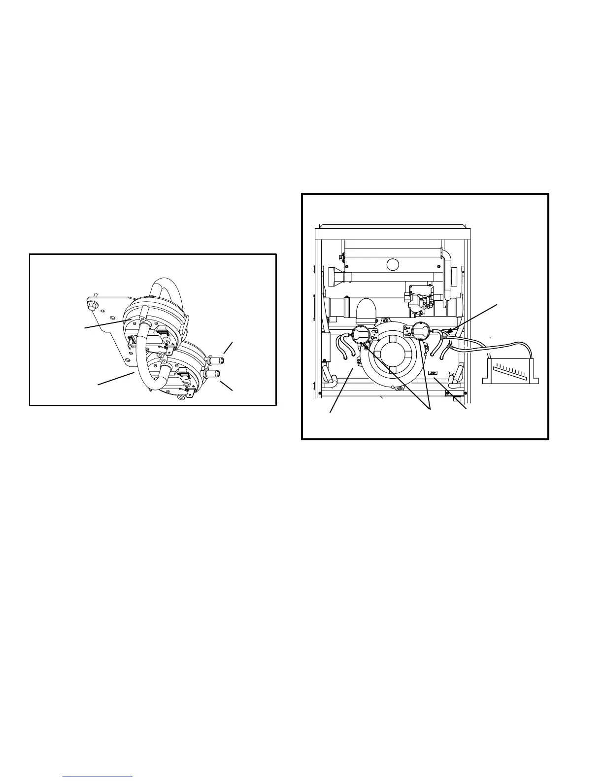
FIGURE 9
DUAL COMBUSTION AIR PROVE SWITCH
G61MP−090, −110 & −135
first stage
second stage
positive
pressure
negative
pressure
To troubleshoot the prove switches, temporarily jumper them.
The unit will not fire with the switches jumpered. Therefore, the
prove switches must be bypassed after the combustion air in-
ducer is activated. This will determine if the prove switches
and furnace are operating properly. However, this may not in-
dicate if the sealed combustion system is operating properly.
Checks of pressure differential can aid in troubleshooting.
When measuring the pressure differential, readings should be
taken at the prove switch. Lack of differential usually indicates
problems in the intake or exhaust piping, but may indicate
problems in the heat exchanger, condensing coil, head-
er boxes, combustion inducer or other components.
Measuring pressure differential
The differential pressure is the difference in pressure mea-
sured across the cold end header box orifice.
1 − Remove thermostat demand and allow unit to cycle
off.
2 − Install a tee in the negative (−) line and a tee in the positive
(+) line running from one of the prove switches to the cold
end header box.
3 − Install a manometer with hose from the negative (−)
side of the manometer to the tee installed in the nega-
tive (−) line and with hose from the positive (+) side of
the manometer to the tee in the positive (+) line.
NOTE − Both sides of the cold end header box are negative.
However the (+) port reads less negative pressure than the
(−) port.
FIGURE 10
Install tee’s in the
negative line and
positive line then
connect hoses to
manometer.
prove switches
orifice size
CAI & COLD END HEADER BOX ASSEMBLY
(−045 & 070 SHOWN)
cold end header box
+
+
_
_
4 − Operate unit and observe manometer reading. Read-
ings will change as heat exchanger warms.
a. Take one reading immediately after start-up.
b. Take a second reading after unit has reached steady
state (approximately 5 minutes). This will be the pres-
sure differential.
The pressure differential should be greater
than those listed in table 8, 9 or 10.
5 − Remove thermostat demand and allow to cycle off.
6 − Remove manometer and tee’s. Reinstall combustion air
sensing hoses to the prove switch.
7 − Repeat steps 1 through 6 for the other prove switch.

 Loading...


