• 14 •
1611
2712
3813
49
14
510
8, 9, 10, 11, 12, 13 4, 5, 6, 7, 8, 9, 10, 11, 12, 13, 14 2, 3, 4, 5, 6, 7, 8, 9, 10, 11,12, 13, 14
8
9
10
11
12
12
12
13
13
1
4
5
6
7
8
9
10
11
12
12
12
14
14
13
13
1´
1
2
3
4
5
6
7
8
9
10
11
12
12
12
11
13
13
14
14
Installation manual /eCOMFORT-MIL150E-0916 / 05/2017
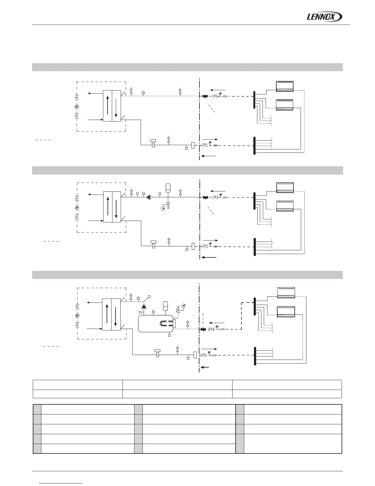
STANDARD UNIT
Customer connection
Hydraulic connections
Inside terminal unit
To be connected by the
installer
Carried out by the
installer
UNIT WITH WATER PUMP OPTION
Customer connection
Hydraulic connections
Inside terminal unit
To be connected by the
installer
Carried out by the
installer
UNIT WITH WATER TANK OPTION
Inside terminal unit
To be connected by the
installer
Carried out by the
installer
Hydraulic connections
Customer connection
COMPONENTS:
STANDARD VERSION UNIT WITH WATER PUMP OPTION UNIT WITH WATER TANK OPTION
Water fi lter (additional option, supplied
loose)
Expansion vessel Drain valve
Water tank Water pump Pressure tap
Water tank heater Air purge valve Water temperature sensor
Safety valve Plate exchanger
Pressure transducer (when variable water fl ow
option is selected)
Pressure gauge Flow switch
1.- GENERAL CHARACTERISTICS
1.3.- COMPONENTS
The eComfort system comprises a water cooler or air/water pump combined with a series of hydraulic accessories.
The use of a water fi lter in the water circuit upstream of the heat exchanger is mandatory. These fi lters must remove all particles with a diameter greater than 1 mm, and must
be positioned within 1 meter of the inlet of the exchanger. They may be supplied as an option by the manufacturer.
 Loading...