• 46 •
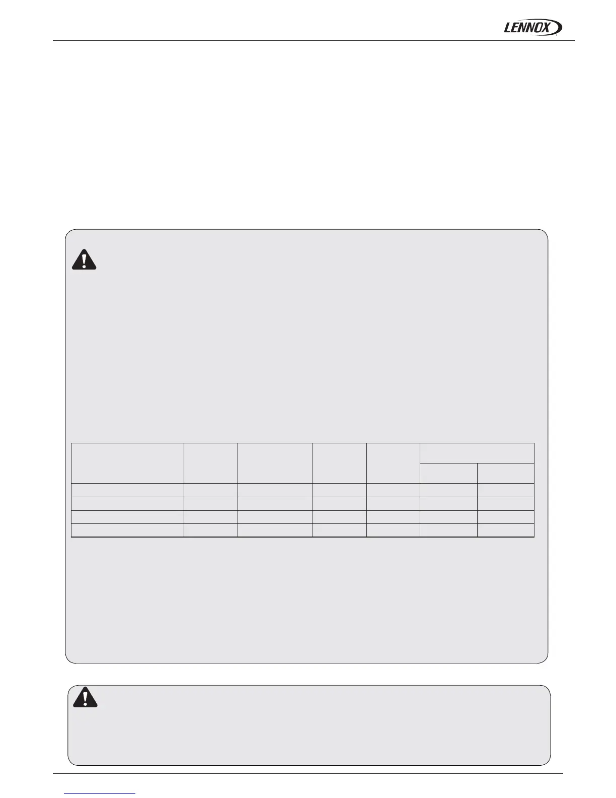
10% 1,05 1,02 0,997 0,995 0,994
20% 1,10 1,05 0,996 0,985 0,993
30% 1,15 1,08 0,995 0,975 0,99
35% 1,18 1,10 0,994 0,965 0,987
Installation manual /eCOMFORT-MIL150E-0916 / 05/2017
Minimum ambient
temperature or water outlet
temperature
Ethylene
Glycol %
Pressure drop Water fl ow Power input
Capacities
Cooling mode Heating mode
From +5ºc to 0ºc
From 0ºc to -5ºc
From -5ºc to -10ºc
From -10ºc to -15ºc
IMPORTANT
If the outside temperature in the area where the eComfort unit is to be installed is likely to drop below 5°C, it is very
important to take the following precautions to avoid that water in the circuit freezing, that may produce damage to the
components.
- If unit has to work under low outside temperatures:
* Do not disconnect power supply in order that water pump starts when detects water temperatures below +5 ºC (only
Hydraulic and Hydronic models).
* If the outside temperature where the system is to be installed or the water outlet temperature is likely to drop below
5ºC, it is very important to use glycol anti-freeze.
The amount of anti-freeze required will vary depending on the minimum ambient temperature or the water outlet
temperature.
When the percentage of glycol increases the standard pump fl ow decreases, the pressure drop increases and the
cooling and thermal capacities drop. As a result the minimum fl ow must be multiplied by the coeffi cient shown in the
table:
Also is advisable to use the option “evaporator anti freeze protection”
Failure to follow this advice, may result in damage to the installation.
Optionally, an immersion heater can be supplied complete with safety thermostat and pressure switch fi tted in the
buffer tank of the cooling only chiller. A similar option is available for heat pump versions with the added advantage of a
supplementary heating source (Hydronic version units).
2.- INSTALLATION
Legislation does not allow refrigerant gas emissions to the atmosphere, so the refrigerants have to be
recycled to avoid being released to the aosphere.
Those recycled refrigerants shall be processed afterwards by an authorized waste manager.
Those components derived from the recycling of the unit have to be managed by authorized waste
manager or be left in local waste facilities according the local normative in each country.
For location inside, keep in mind following advice:
- In heat pump units during defrost cycle, the units produce a great amount of water melting the ice off coils.
If you wish to drain the water, adequate drainage should be installed below the unit to collect and carry out the water where
desired.
- Air duct installation:
If air duct has been installed, the operating limits get reduced
10. For cooling or heat pump units the hydraulic system must contain the following components pump, buffer tank, expansion
device, safety valve, water fi lter, fl ow switch.
11. To obtain the total water system pressure drop add the unit pressure drop + water pipework + fi ttings and terminal unit
pressure drops the water pump can be selected to provide the correct water fl ow across the heat exchanger.
12. A water balancing valve is advised to ensure correct water fl ow.
 Loading...