• 51 •
Installation manual /eCOMFORT-MIL150E-0916 / 05/2017
3.- COMMISSIONING AND OPERATION
3.2.- STEPS TO FOLLOW FOR CONTROL SETTING
7. Remote control connection (on/off, cool/heat, alarm)
(3141): BM-ID3 digital input confi guration setting
(3142): BM-ID4 digital input confi guration setting
(3131): BM-NO1 output relay confi guration setting
8. BMS confi guration (address, baud rate)
(3825): Watchdog for activation of the BMS mode
(3826): BMS address
(3827): BMS protocol
(3828): BMS baud rate
(3829): BMS Modbus RTU format
II. Test
• Check electrical connections
- (power supply & phase order)
- External connexions (customer inputs/relays/displays)
- Check the thermal protection of the circuit brakers. Watch out the Condenser fans circuit breaker protection will be 2xImax
• Check water fi lter & hydraulic connections
• Open the unit and check inside
• Power-up the unit
1. Evaporator pump
(3114)= ‘Pump Evap’ (1 or 2 in case of double pump)
• Check the fl ow switch status in the menu (2218)
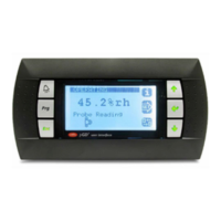
• Check the electrical consumptions (in case of variable pump in the pump technical service screen pressing PRG)
• Check the evaporator DP in menus
After this test, check fl ow switch opens
2. Condenser fan
(3114)= ‘C*.Fan.LS’ (low speed)
(3114)= ‘C*.Fan.HS’ (high speed)
(3114)= ‘C*.100%’ (modulating speed)
• Check the electrical consumptions (in case of EC fan in the fan technical service screen pressing PRG)
3. Frigorifi c circuit test
Cooling mode
(3114)=’C1.Cool’
• Check the circuit pressures and temperatures
• Check the electrical consumptions
(3114)=’C2.Cool’
• Check the circuit pressures and temperatures
• Check the electrical consumptions
Heating mode
(3114)=’C*.Heat’
• Check the circuit pressures and temperatures
• Check the electrical consumptions
4. HP cut off
(3114)=’HP Cut-Off C*’
5. Electrical auxiliary heater
(3114)=’Auxiliary heater’
• Check the inlet / outlet temperatures
• Check the electrical consumptions
6. Electrical antifreeze heater
(3114)=’Antifreeze heater’
• Check the control voltage on the TRIAC (10vdc)
 Loading...