18
240012994 Rev. B [08/31/2020]
5 - COMBUSTION AIR AND VENT PIPING
Twin Pipe Maximum Vent Lengths
(Includes rst elbow and termination)
Boiler
150 205
All
Vent Size
3"
[80 mm]
2"
[60 mm]
3"
[80 mm]
2"
[60 mm]
All
Maximum Minimum
Intake
Vent
L1
49 ft
[15m]
85 ft
[25.9m]
100 ft
[30.5m]
85 ft
[25.9m]
6 ft
[1.8 m]
Exhaust
Vent
L2
147 ft
[45m]
Combined
Vent
L1+L2
196 ft
[60m]
170 ft
[51.8m]
200 ft
[60.9m]
170 ft
[51.8m]
12 ft.
[3.6 m]
Single Wall Elbows - Equivalent Length
3" (80 mm) 2" (60 mm)
45° bend
0.82 ft [0.25 m] 3 ft [0.91 m]
90° bend
1.64 ft [0.50 m] 5 ft [1.5 m]
NOTE: Two pipe can be installed horizontally or vertically.
5.8 Twin Pipe Systems
Twin pipe venting allows exhaust ue and intake ue to be
separated from each other. Fresh air is drawn in at a dierent
area from the ue terminal location.
A.
Twin Pipe CPVC System
CPVC is approved for boiler exhaust. CPVC or PVC are both
approved for air intake.
To transition from Coaxial at the top of the boiler to Twin Pipe
CPVC/PVC a kit is available.
B.
Twin Pipe Polypropylene System
Single wall polypropylene is used for both exhaust and air
intake piping.
To transition from Coaxial at the top of the boiler to Twin Pipe
polypropylene venting an adapter kit is available.
C.
Twin Pipe Separated Flue
Exhaust and combustion air intake are not located in same
general location.
D.
Twin Pipe - Common Atmospheric Zone
Termination
Exhaust and combustion air intake are located in same
general location and are of equal length.
Grade, Snow
& Ice
Maintain 12"(305 mm) US, 18"(457
mm) Canada clearance above highest
anticipated snow level, 24" (610 mm)
above roof.
Avoid locations where snow may drift
and block vent and combustion air.
Ice or snow may cause boiler to shut
down if vent or combustion air becomes
obstructed.
WARNING
Asphyxiation hazard! Improper installation could
result in death or serious injury. Read Twin Pipe
Installation Instructions completely and understand all
requirements before beginning installation.
!
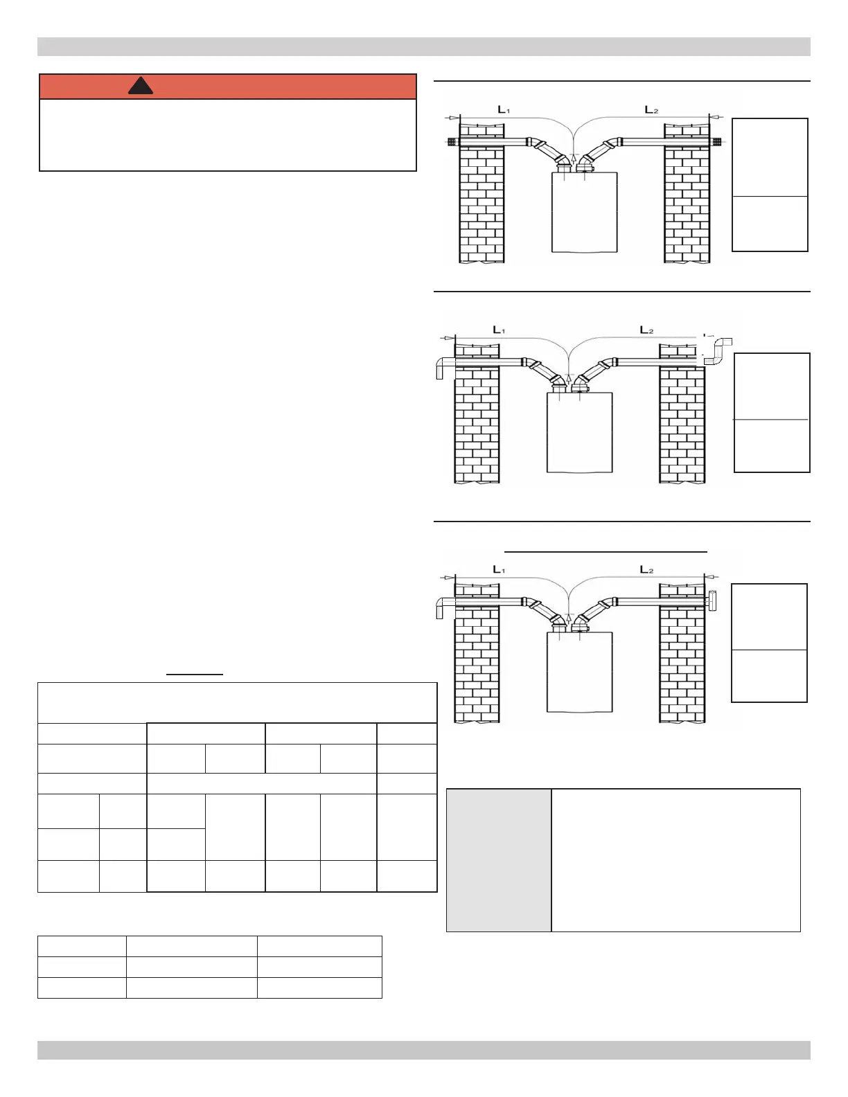
FIGURE 5-8 - 2"/60 mm & 3"/80 mm Twin Pipe
Separated Horizontal Flue Termination
FIGURE 5-9 - 2"/60 mm & 3"/80 mm Twin Pipe
Separated Horizontal Flue Termination
FIGURE 5-10 - 2"/60 mm & 3"/80 mm Twin Pipe
Separated Horizontal Flue Termination With Tee On
Exhaust - CAN BE USED ON ALL SIZES
This Termination
can be used on:
2" / 60 mm ON
205
3" / 80 mm
ON ALL SIZES
vent only
This Termination
can be used on:
2" / 60 mm
ON ALL SIZES
3" / 80 mm
ON ALL SIZES
vent only
This Termination
can be used on:
2" / 60 mm ON
205
3" / 80 mm
ON ALL SIZES
vent only
When using charts below
See Vent Material Options - page 15
 Loading...