35
240012994 Rev. B [08/31/2020]
8 - ELECTRICAL CONNECTIONS
8.4 Access To Connection Block
1.
Ensure there is no line voltage at boiler.
2.
Unscrew two screws located under front panel. Remove
front cover.
3.
Guide controller or thermostat wire through round
grommet(s) on right side of boiler's bottom plate.
4.
Tilt control box forward by opening holding clip located on
left side of control housing.
5.
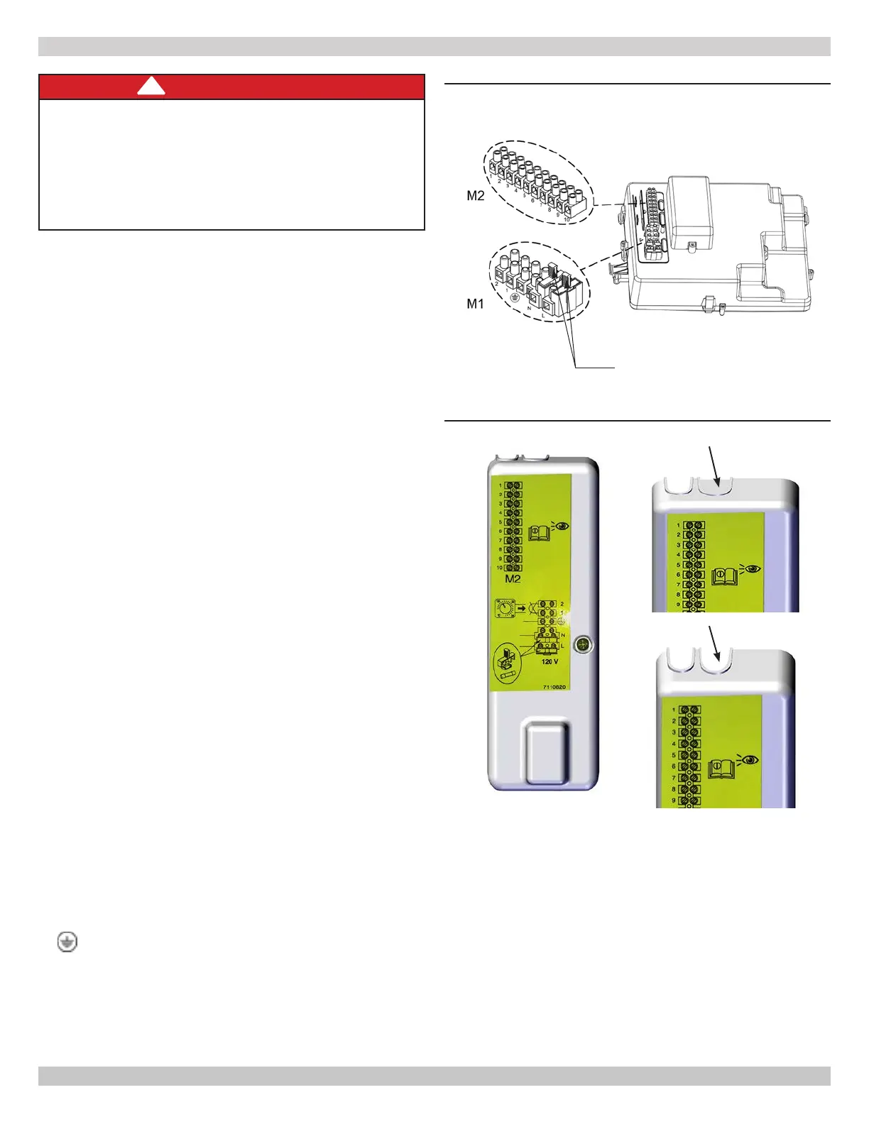
Expose M1 and M2 terminal blocks by removing screw
from plastic cover on left. See Figure 8-3.
6.
Remove plastic from channel in plastic cover. Run wires
through new opening.
7.
Connect wires to appropriate terminals on connection
block.
8.
Reinstall electrical cover plate.
9.
Tilt control box back to original position. Ensure clip on
left side is fully engaged.
10.
Replace front cover and screws under front panel.
11.
Turn power to boiler on.
Dry contact end switches from various manufacturers can be
attached to boiler control PCB.
8.5 Main Supply Connection
Main supply is connected to terminal block M1 which is high
voltage (120V / 60Hz).
Fuses, 3.15 A, 250 V, Fast Acting, are incorporated in the
power supply terminal block. To check or replace fuse pull out
black fuse carrier.
TERMINAL BLOCK M1
(L) = Live (brown)
(N) = Neutral (light blue).
= Ground (yellow-green).
(1) (2) = contact for 120V Room Thermostat.
Place jumper back on terminals 1-2 of boiler terminal block
M1 if room thermostat is not used or if Remote Control is
not installed.
FIGURE 8-2 Terminal Block Locations
Fuse Holders (2)
DANGER
Electrocution Hazard! HIGH VOLTAGE - Connections
in terminal block M1 are high voltage (120V / 60Hz).
Before making connections, verify appliance is
disconnected from power supply. Respect the input
polarity on terminal block M1: L (LINE) - N (NEUTRAL).
Failure to follow these instructions WILL result in death
or serious injury.
!
TERMINAL BLOCK M2
Terminals 1 - 2: Bus connection for Argo communicating
thermostat (supplied as an accessory)
Terminal 4 - 5: outdoor temperature sensor connection
(supplied as an accessory)
Terminals 6 - 7 - 8: Dry Contact End Switch
Terminals 9 - 10: 0 - 10V connection
FIGURE 8-3 Terminal Plastic Cover with Knockouts
Remove
New Opening
 Loading...