36
240012994 Rev. B [08/31/2020]
8 - ELECTRICAL CONNECTIONS
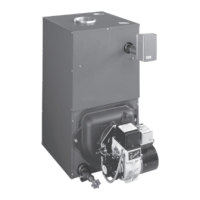
A. Connect Room End Switch
• turn power o to boiler;
• access terminal block M2;
• connect room end switch to terminals 6(R)-7(W)-
8(C); Do not apply voltage between 2 terminals. Dry
contact only.
• turn boiler power on;
• verify room end switch operates per end switch
manufacturer instructions.
NOTE: maximum load allowed is 10 mA
Dry contact end switches from various manufacturers can be
attached to boiler control PCB.
FIGURE 8-4 Thermostat Connections
8.6 Install Room Thermostat
Install room thermostat on inside wall. Do not install where it
will be inuenced by drafts, hot or cold water pipes, lighting
xtures, television, sun rays or near a replace.
Dry contact only - do not apply 24 volts between 6 and 7.
A
Room End
Switch
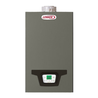
8.7 Optional Electrical Connections
A. 1K Ohm (1K Ω) Outdoor Temperature Sensor
To connect this accessory, see gure 8-5, terminals 4-5, and
instructions supplied with
1K Ω sensor.
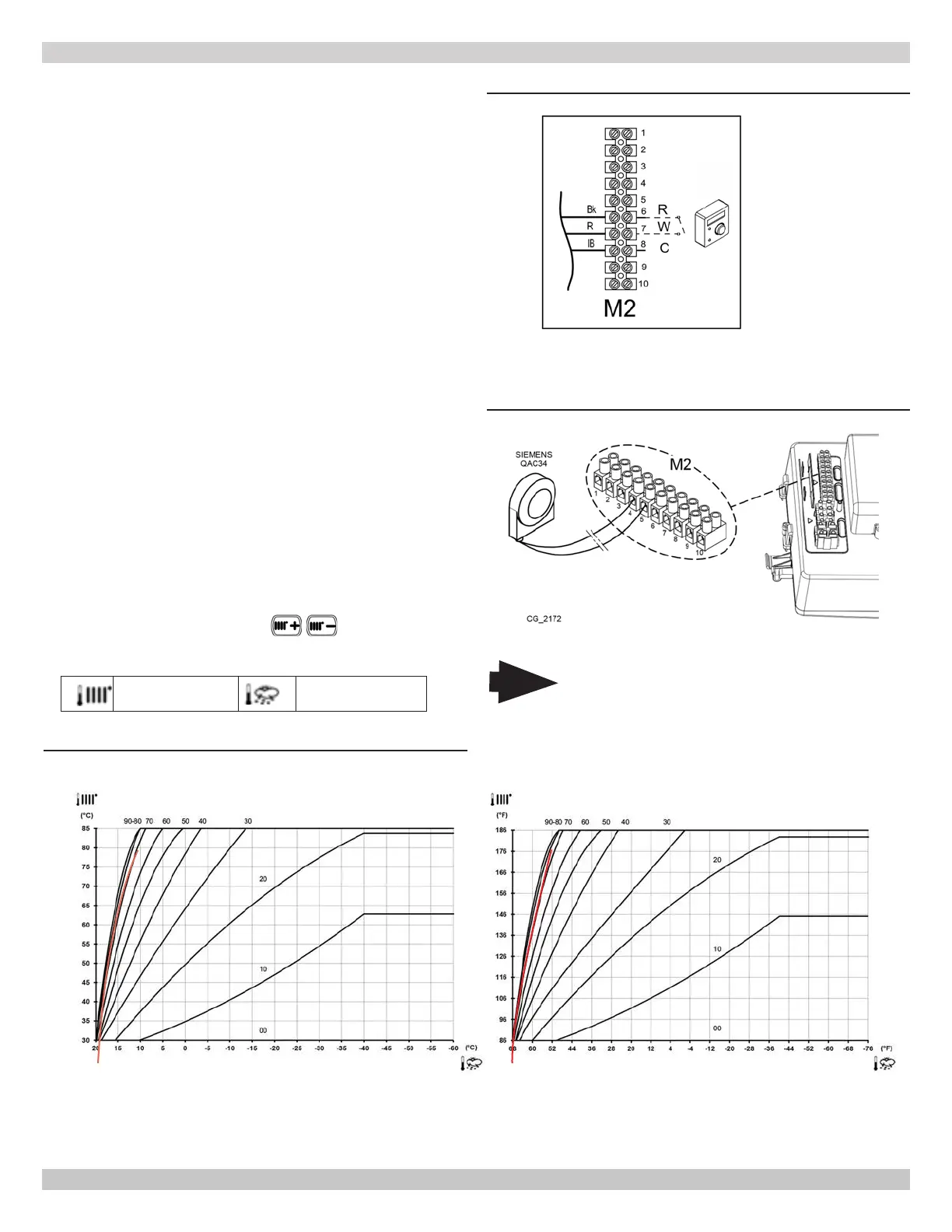
B. Setting "Kt" Climate Curve
When external
1K Ω sensor is connected to boiler, the
electronic board adjusts the ow temperature calculated
according to set Kt coecient.
Select required curve by pressing
as indicated in
chart below for selecting the appropriate curve (00 to 90).
Flow temp Outside temp
NOTE:
Temperatures below -40 °F (-40 °C), maximum heating ow temperature set point no longer increases, curves shown on graph
become horizontal.
Boiler set-point will override sensor set-point.
FIGURE 8-5 Outdoor Sensor Connections
FIGURE 8-6 Kt Climate Curves
80 Is Default.
Note
Sensors used for this boiler are proprietary to
the manufacturer. Use of after market sensors
will diminish boiler performance.
1K Ω
 Loading...