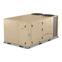
Do you have a question about the Lennox LDT DUAL FUEL Series and is the answer not in the manual?
| Brand | Lennox |
|---|---|
| Model | LDT DUAL FUEL Series |
| Category | Air Handlers |
| Language | English |
Essential safety warnings for operation, maintenance, and electrical hazards.
Overview of the LDT commercial combination heat pump and gas unit.
Detailed performance data for cooling and heating capacities across models.
Specs for coils, blowers, and electrical characteristics of LDT units.
Input/output capacities, temperature rise, and thermal efficiency.
Derating guidelines for gas manifold pressure at higher altitudes.
Static pressure resistance data for various air volumes and unit configurations.
Electrical ratings for compressors, fans, and components for 6.5 Ton models.
Electrical ratings for compressors, fans, and components for 7.5 Ton models.
Illustration showing the physical layout of major LDT unit components.
Visual identification of components within the unit's main control box.
Descriptions of transformers, relays, and switches in the control box.
Safety guidelines for handling electronic components to prevent ESD damage.
Visual representation of refrigerant flow paths for different LDT unit models.
Details on compressors, freezestats, and pressure switches for system protection.
Key operational notes on compressor protectors and their behavior.
Explanation of reversing valve function and defrost switch operation.
Information on filter driers, fan motors, heaters, and sensors.
Procedures for accessing and servicing the blower compartment.
Steps for calibrating the blower and adjusting cooling speeds via the controller.
A table detailing adjustable parameters for blower speed and operation modes.
Details on the heat exchanger, inserts, and burner box assembly.
Information on burner type, factory settings, and basic maintenance.
Orifice sizing, primary limits, and combustion air switches.
Operation of the combustion air inducer and its related safety controls.
Description of gas valve operation and spark electrode assembly.
How the flame sensor detects ignition and ensures safety.
Details on the burner control board and its diagnostic LED codes.
Normal and retry ignition sequences with specific timing information.
Essential pre-operation checks and seasonal maintenance procedures.
Steps for initiating heat pump operation based on ambient temperature.
Warnings regarding explosion, electric shock, and smoke potential during operation.
Procedures for gas valve operation and safely placing the unit into service.
Procedures for cooling startup and ensuring correct compressor voltage phasing.
Steps for safely shutting down the unit in emergency situations.
Methods for charging and checking refrigerant levels using pressure readings.
Using subcooling measurements to verify correct refrigerant charge.
Guidelines for gas piping installation and leak detection methods.
Procedures for testing natural and propane gas supply pressure at the unit.
Adjusting manifold pressure for proper gas flow and stable flame.
Flame sensing procedures and cooling system service checks.
Instructions for cleaning air filters, indoor, and outdoor coils.
Maintenance for the blower wheel and filter drier replacement.
Details on roof mounting frames and duct transitions for installation.
Information on air diffusers and optional outdoor air damper accessories.
Configuration of different economizer operating modes and setpoints.
Function and installation of barometric relief dampers for air discharge.
Operation and setpoint adjustment for the power exhaust fan.
Operation of enthalpy controller and various thermostat switches.
Details on LP/Propane kits and cold weather kits for unit operation.
Wiring schematic for gas heat operation with Y voltage supply.
Wiring schematic for gas heat operation with J voltage supply.
Step-by-step operation for first and second stage heating modes.
Wiring diagram detailing thermostat connections to the unit controller.
Schematic for connecting economizer sensors and control wiring.
Wiring diagram illustrating Y voltage supply and control circuits.
Wiring diagram illustrating G voltage supply and control circuits.
Wiring diagram illustrating J voltage supply and control circuits.
Step-by-step operation for first and second stage cooling modes.
Heating operation logic based on ambient temperature and demand.
Conditions and timing for initiating the unit's defrost cycle.
Sequence of operation for the direct drive blower motor.
Procedures for diagnosing and resolving common blower faults.
 Loading...