EasyManuals Logo

Lennox LGM Series Unit Information

Lennox LGM Series
54 pages
To Next Page IconTo Next Page
To Previous Page IconTo Previous Page
Page #17 background imageLoading...
Page #17 background image
Page 17
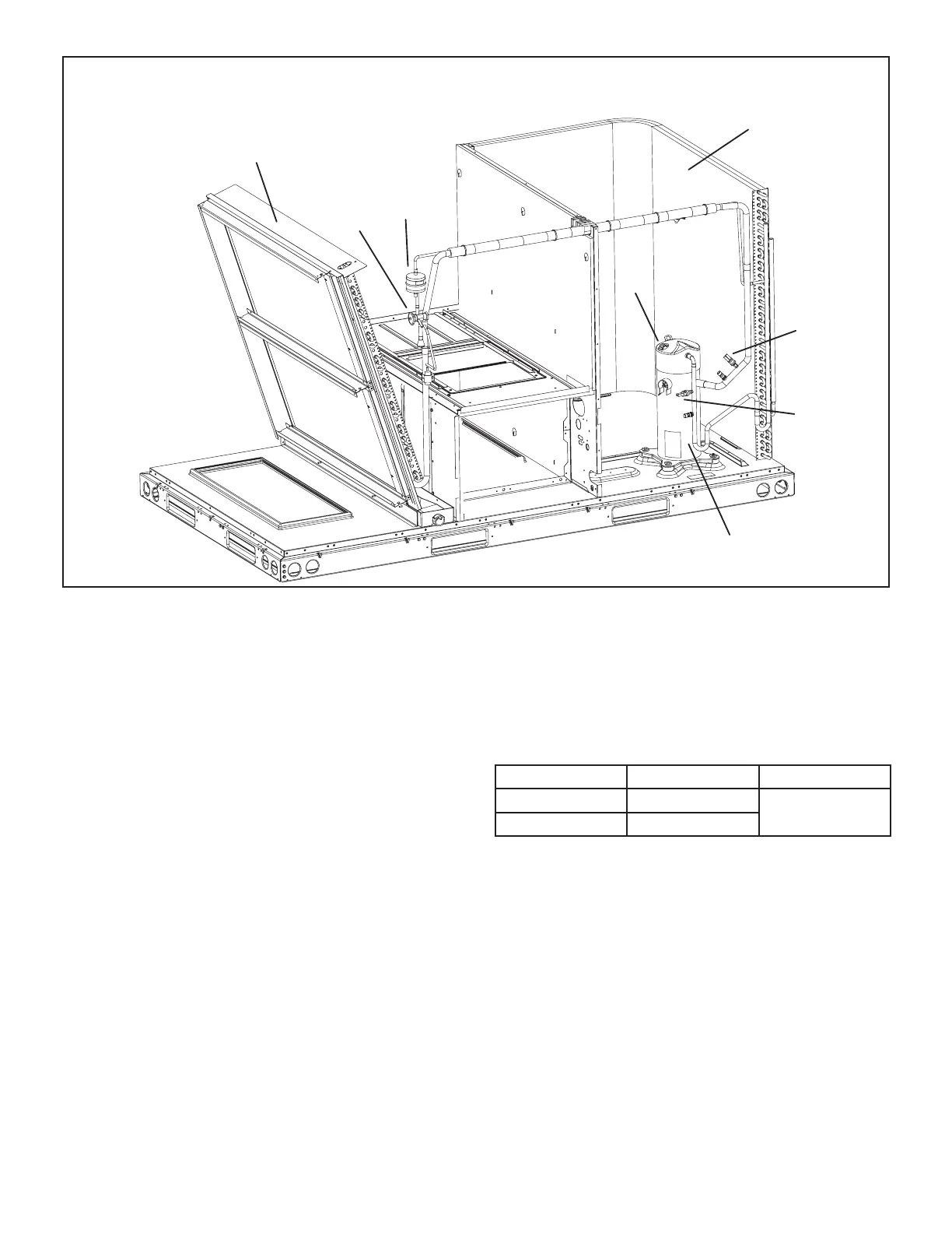
PLUMBING AND COMPRESSOR PROTECTION COMPONENTS
EVAPORATOR COIL
CONDENSER COIL
DRIER
COMPRESSOR
RETURN AIR
SECTION
INDOOR
BLOWER
SECTION
EXPANSION
VALVE
HEAT
SECTION
S5
S87
S4
FIGURE 5
4-Thermistors
Units are equipped with four factory-installed thermistors
󰀨
on the refrigerant circuit.
The thermistors provide the Unit Controller with constant
-
frigeration circuit. These temperatures are used as feed-
back in certain modes of unit operation. In addition, the
Unit Controller uses these temperatures to initiate alarms

of charge.

operation and to initiate valid alarms. See table 1 for prop-
er locations.
TABLE 1
THERMISTOR LOCATION
Unit RT42 & RT46 RT44 & RT48
036U, 048U Figure 6
Figure 8
060U, 074U Figure 7

Other manuals for Lennox LGM Series

Questions and Answers:

Question and Answer IconNeed help?

Do you have a question about the Lennox LGM Series and is the answer not in the manual?

Lennox LGM Series Specifications

General IconGeneral
BrandLennox
ModelLGM Series
CategoryFurnace
LanguageEnglish

Related product manuals