Page 29
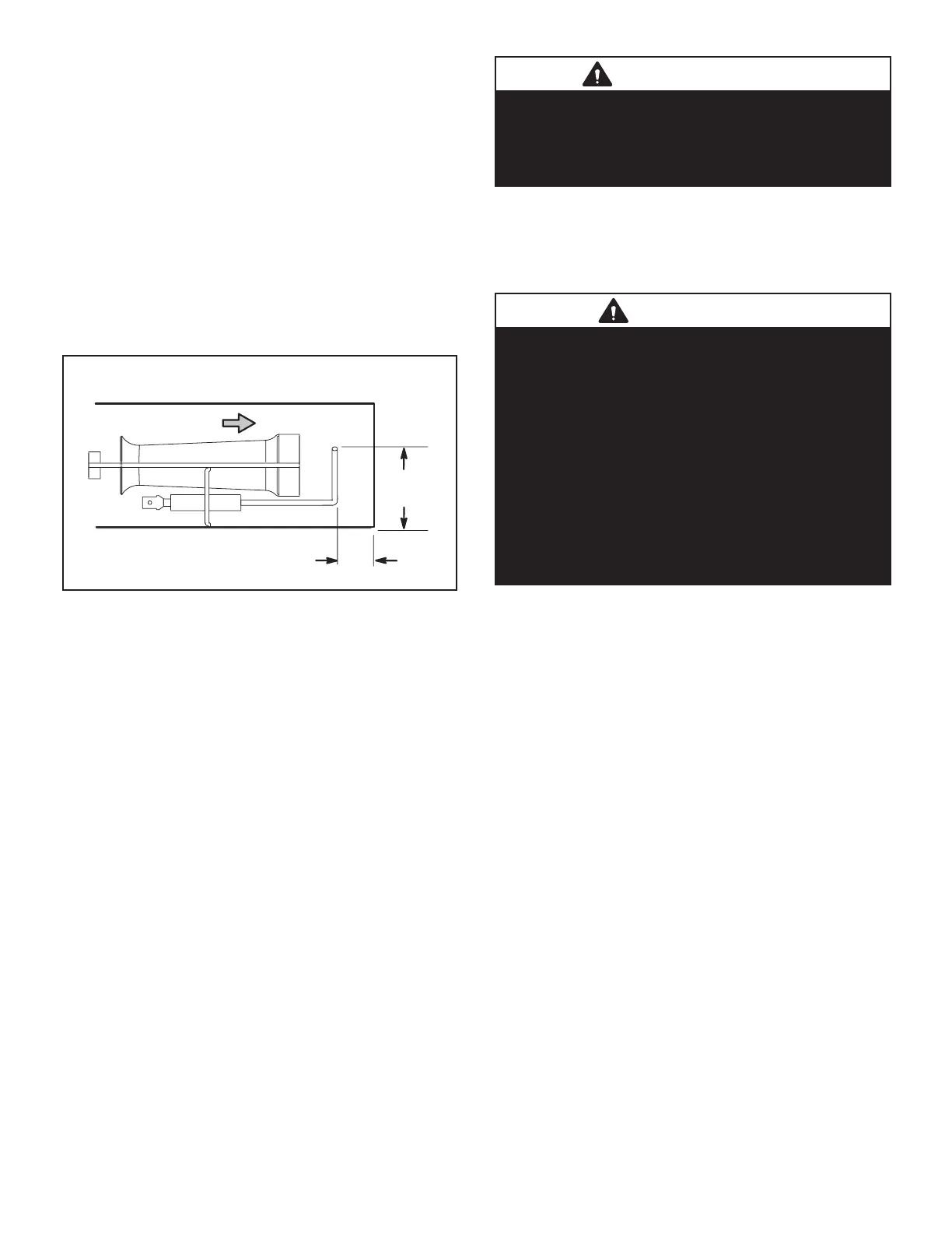
11-Flame Sensor Figure 20
-
sensor assembly is fastened to burner supports and can
be removed for service without removing any part of the
burners.
-
diately or after the eight second trial for ignition. During
ground electrode (located on the spark electrode), through
-
SIDE VIEW SENSOR
1-3/4”
(45mm)
3/8”
(10mm)
Gas Flow
FIGURE 20
D-BLOWER COMPARTMENT
Units are equipped with a variable speed, direct drive
-
cy. The Unit Controller calibrates the supply air volume
which eliminates the need to manually take duct static
measurements.
1-Indoor Blower Motor B3
All direct drive blower motors are electronically commutat-
ed, brushless, DC motors. The motors are powered with
high voltage 3-phase AC power. CFM adjustments are
made by changing Unit Controller parameters via the ser-
vice app. Motors are equipped with sealed ball bearings.
(table of contents) in the front of this manual. Motors come
with pre-mounted aluminum impellers.
IMPORTANT
Three phase scroll compressors must be phased
sequentially for correct compressor and blower
rotation. Follow “COOLING START-UP” section
of installation instructions to ensure proper
compressor and blower operation.
A-Blower Operation
Refer to the Unit Controller Setup Guide to energize blow-
TEST.
WARNING
1-Make sure that unit is installed in accordance with
the installation instructions and applicable codes.
2-Inspect all electrical wiring, both eld-and
factoryinstalled, for loose connections. Tighten as
required.
3-Check to ensure that refrigerant lines do not rub
against the cabinet or against other refrigerant lines.
4-Check voltage at disconnect switch. Voltage
must be within range listed on nameplate. If not,
consult power company and have voltage condition
corrected before starting unit.
5-Make sure lters are new and in place before
startup.
B-Determining Unit CFM
CFM is calculated using a supplied pressure transducer
and can be viewed in the mobile service app. CFM can
also be manually checked as follows:
1 - The following measurements must be made with air
IMPORTANT - A low speed adjustment less than 2/3
of high speed will improve humidity removal; refer to
product data for more information.
2 - With all access panels in place, measure static
pressure external to unit (from supply to return).
Blower performance data is based on static pressure
Note - Static pressure readings can vary if not taken
where shown.
3 - Measure the indoor blower wheel RPM.
4 - Referring to the blower tables in the front of this
manual, use static pressure and RPM readings to
determine unit CFM. Apply the optional accessory
air resistance.

 Loading...

