Page 28
8-Combustion Air Inducer B6
Combustion air inducers provide air to the corresponding
burners while clearing the combustion chamber of ex-
haust gases. The inducer begins operating immediately
upon receiving a thermostat demand and is de-energized
The inducer uses a 208/230V single-phase PSC motor
at 3300RPM and are equipped with auto-reset overload
protection. Two-speed units have reduced RPM for low
speed. Inducers are supplied by various manufacturers.
-
trical ratings can be found on the unit rating plate.
The ignition control board energizes an internal relay to
route power to the combustion air blower motor. A3 then
allows 30 to seconds for the combustion air inducer to vent
exhaust gases from the burners. When the combustion air
inducer is purging the exhaust gases, the combustion air
prove switch closes, proving that the combustion air in-
ducer is operating before allowing the ignition sequence to
continue. When the combustion air prove switch is closed
and the delay is over, the A3 ignition control activates the
appropriate stage operator of the gas valve, the spark and
for ignition.
On two-stage natural gas units, the inducer will operate
speed for second stage heat (W2).
All combustion air inducer motors are sealed and cannot
be oiled. The inducer cannot be adjusted but can be re-
moved from the heat section for cleaning.
9-Gas Valves GV1
Units are equipped with a two-stage gas valve. When a
heating demand is present, the valve is energized in low
electrode.
both stages without delay.
adjustable. Figure 23 shows gas valve components. Table
4 shows factory gas valve operating manifold pressures.
TABLE 4
Operating Pressure (outlet) Factory Setting “W.C
Natural LP
Low High Low High
2.0 + 0.3” + 0.3 + 0.3 +
The gas manifold pressure should be adjusted when the
unit is installed at altitudes higher than 2000 feet. See
HIGH ALTITUDE table in SPECIFICATIONS - GAS HEAT
10-Spark Electrode (Ignitor) Figure 19
An electrode assembly is used for ignition spark. The
electrode is inserted through holes in the burner support.
envelope of the adjacent burner. The electrode assembly
is fastened to burner supports and can be removed for
service without removing any part of the burners.
During ignition, spark travels through the spark electrode
on the heating stage. Flame travels from burner to burner
until all are lit.
The spark electrode is connected to the ignition control by
a 8 mm silicone-insulated stranded high voltage wire. The
ends of the wire.
NOTE - If electrode wire must be replaced, wire and sup-
pression must be same type cable.
The spark electrode assembly can be removed for inspec-
tion by removing the screw securing the electrode assem-
bly and sliding it out of unit.
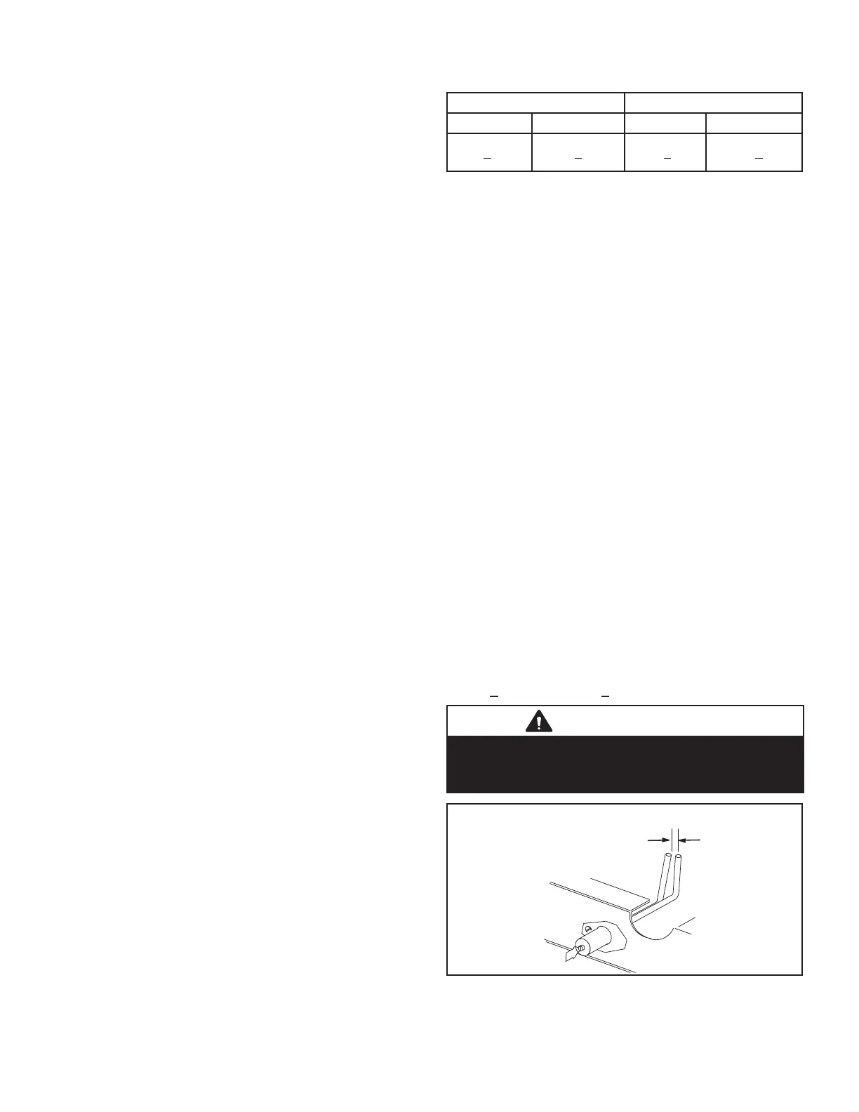
For proper unit operation, electrodes must be positioned
and gapped correctly.
Spark gap may be checked with appropriately sized twist
drills or feeler gauges. Disconnect power to the unit and
remove electrode assembly. The gap should be between
++
IMPORTANT
In order to maximize spark energy to electrode, high
voltage wire should touch unit cabinet as little as
possible.
SPARK GAP
SHOULD BE 1/8”
(3mm)
FIGURE 19

 Loading...

