Page 41
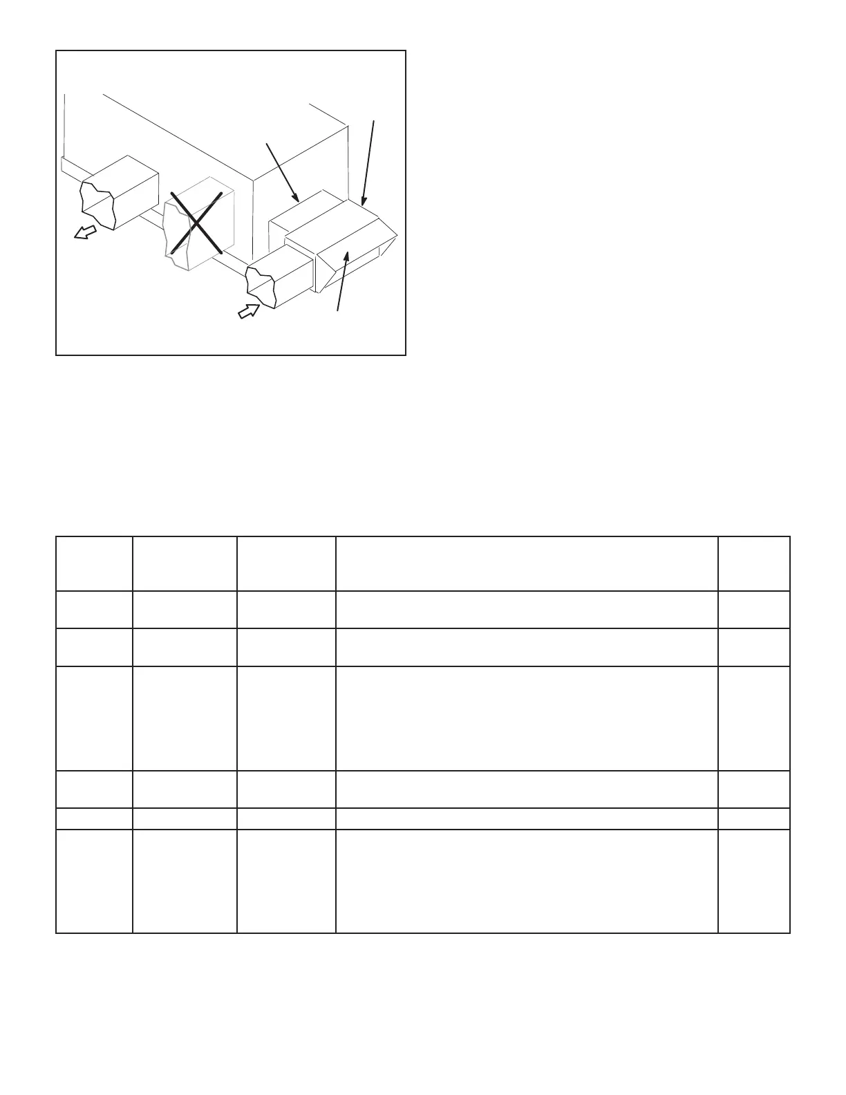
HORIZONTAL AIRFLOW
BACK
OF UNIT
DO NOT ATTACH
RETURN AIR
DUCTWORK
HERE
SUPPLY
AIR
RETURN
AIR
DUCT
TRANSITION
DUCT
INLET
OPTIONAL GED
DAMPER AND HOOD
FIGURE 34
TABLE 12
ECONOMIZER MODES AND SETPOINT
Free|
Cooling
Mode
Free
Cooling
Setpoint
Field-
Provide
Sensors
Dampers will modulate to 55°F discharge air (RT6) when
outdoor air is suitable:
Permitted
Inputs
TEMP OFFSET None Needed
Outdoor air temperature (RT17) is less than return air tem-
perature (RT16) by at least the OFFSET value.
TEMP OAT STPT None Needed
Outdoor air temperature (RT17) is less than the OAT STPT
value.
Remote Remote
Eneergy
Management
System**
Either of the TEMP modes can be used when a network
OAS signal is provided by an energy management or build-
ing control system, via BACnet, LonTalk, or L Connection.
The network can command OAS, NOT OAS, or AUTO.
AUTO returns to local control of OAS, which is the selected
TEMP mode.
NA
ENTH DIFF OFFSET (Two) C7400
Outdoor air enthalpy* (A7) is less than return air enthalpy
(A62) by at least the OFFSET value.
0mA-4mA
ENTH ODE STPT C7400 Outdoor air enthalpy (A7) is less than free cooling setpoint. 12-19mA
GLOBAL GLOBAL
24VAC Input
Signal
Global input is energized by (P297-9). This setting is also
used for outdoor air damper applications. Global input also
brings on the blower. (This mode is NOT used when OAS
signal is provided via network connection. GLO is only used
when a 24VAC signal is used to energize the P297-9 GLO
input.)
NA

 Loading...

