Page 17
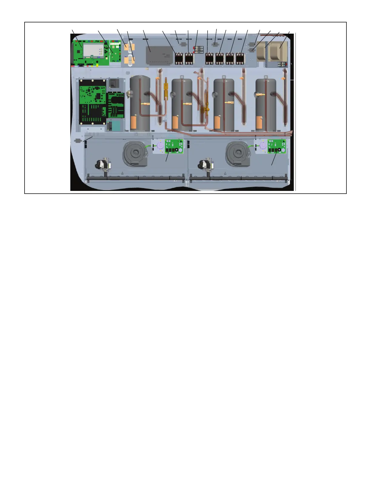
M4 (A55)
A178T1T18 A96 K203K202K3F10 K1 K191K2 K14 K146 K65
K231
A12
A3
K9
T59
(G volt
T5
(G volt)
VSC Inverter
FIGURE 3
4-Terminal Block TB13
TB13 terminal block distributes line voltage power to the
line voltage items in the unit.
5-Outdoor Fan Motor Fuse Block & Fuses F10 Power
Exhaust Fan Motor Fuse Block and Fuses F6.
STD SCCR 240V, 300V and higher rated SCCR units
have three line voltage fuses F10 provide overcurrent pro-
provide overcurrent protection to the two optional power
exhaust fans. The fuses are rated at 30A in all 208/230V
units but 10A in the 208/230V 240U and 300U models.
6-Compressor Contactor K1, K2, K14, K146
K1, K2, K14: All units
All compressor contactors are three-pole-double-break
contactors with 24VAC coils. K1 and K2 (energized by
A55) energizes compressors B1 and B2 in response to
A178) energizes B13 in response to second stage cool
-
ergized by A178) energize compressors B13 and B20 in
response to second stage cool demand.
7-Blower Contactor K3
Blower contactor K3, used in all units, is a three-pole-dou-
blebreak contactor with a 24VAC coil used to energize
the indoor blower motor B3 in response to blower de-
mand. K3 is energized by Unit Controller (A55). Optional
Staged-Blower units which are not equipped with a by-
pass option will not have a K3.
-
cept 208/230V and 575V which are equipped with a UVC.
The auto voltage to 230VAC transformer is installed in
the control box. The transformer has an output rating of
UVC lamp.
9-Burner Controls A3 & A12
Units have two burner controls. A3 controls gas heat sec-
gas heat section and the second gas heat section burner
controls are identical. Both burner controls are factory set
and are not adjustable. The control makes three attempts
at ignition and then locks out the system if ignition is not
obtained after the third trial. Reset after lockout requires
only breaking and remaking thermostat demand. The con-
or power failure. Upon restoration of gas and power, the
control will restart the ignition sequence and continue until
lame is established or system locks out. For a more de-
tailed description see the Gas Heat Components section.

 Loading...

