Page 18
relays with a 24VAC coil. The relay are used in units
and K231 are energized by the A55 Unit Controller, after
the economizer dampers reach 50% open (adjustable in
and when K231 closes B11 is energized.
Staged-Blower units are equipped with a VFD which alters
the supply power frequency and voltage to the blower mo-
tor. Blower speed is staged depending on the compressor
stages, heating demand, ventilation demand, or smoke
parameters in the A55 Unit Controller. The VFD is located
below the Unit Controller.
Contactor is used in Staged-Blower units equipped with
with a 24VAC coil is energized by the A55 Unit Controller.
K202 allows power from the VFD to the B3 blower motor
in response to blower demand.
13-Inverter Start Forward Rotation Relay K203
Relay is used in optional Staged-Blower units and is a
three-pole double-throw relay with a 24VAC coil. K203 is
energized by the A55 Unit Controller and provides input to
14-Unit Controller A55
The Unit Controller provides all unit control functions, unit
status information, unit diagnostics, programmable pa-
to the Unit Controller guide provided with the unit. Ther-
15-Compressor 3 & 4 Controller A59 & A178
outputs required for compressor and fan control, com-
pressor stage diagnostics and low ambient control. The
M3 unit controller is only compatible with L-Connection
sensors provided with the unit or purchased separately as
show thermistor and pressure transducer readings.
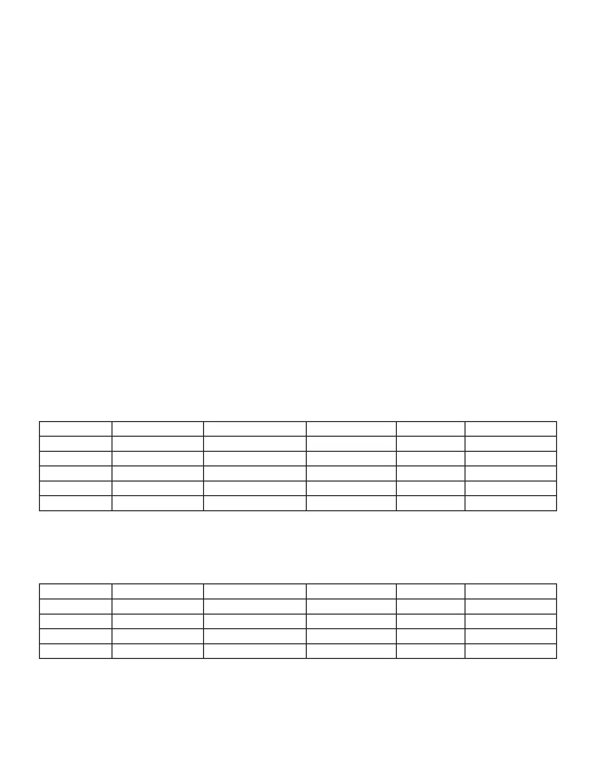
Temperature Sensors
and the outdoor air (RT17) are all two wire thermistors.
The resistance vs. temperature table is shown below:
TABLE 1
Resistance vs. Temperature
Resistance +/-2% Resistance +/-2% Resistance +/-2%
-40 (-40) 40 (4.4) 7,332
50 (10) 100 (37.8)
0 (-17.8) 85,323 15,313
70 (21.1) 11,884 130 (54.4) 3,047
30 (-1.1)
Room Sensors
Room sensor (A2) is a two-wire thermistor with 1k series resistor.
TABLE 2
Two-Wire Thermistor
Resistance +/-2% Resistance +/-2% Resistance +/-2%
40 (4.4) 27,102
45 (7.2) 14,474
50 (10) 70 (21.1) 12,882
55 (12.8) 18,433

 Loading...

