Page 25
IMPORTANT
1-Make sure that unit is installed in accordance with
the installation instructions and applicable codes.
factoryinstalled, for loose connections. Tighten as
required.
3-Check to ensure that refrigerant lines do not rub
against the cabinet or against other refrigerant lines.
4-Check voltage at disconnect switch. Voltage
must be within range listed on nameplate. If not,
consult power company and have voltage condition
corrected before starting unit.
up.
B-Blower Access
1 - Disconnect jack/plug connector to blower motor.
Also disconnect jack/plug connector heating limit
switches on gas units.
2 - Remove screws on either side of blower assembly
3 - Pull base toward outside of unit.
C-Determining Unit CFM
IMPORTANT - Multi-staged supply air units are factory-
set to run the blower at full speed when there is a blower
(G) demand without a heating or cooling demand. Refer
to the eld-provided, design specied CFM for all modes
of operation. Use the following procedure to adjust motor
pulley to deliver the highest CFM called for in the design
spec. See Inverter Start-Up section to set blower CFM for
all modes once the motor pulley is set.
1 - The following measurements must be made with
a dry indoor coil. Run blower (G demand) without
a cooling demand. Measure the indoor blower
measurements are taken.
Note - Static pressure readings can vary if not taken
where shown.
2 - With all access panels in place, measure static
pressure external to unit (from supply to return).
Blower performance data is based on static pressure
3 - Accessories. Use static pressure and RPM readings
to determine unit CFM.
4 - The blower RPM can be adjusted at the motor pulley.
Loosen Allen screw and turn adjustable pulley
clockwise to increase CFM. Turn counterclockwise
minimum and maximum number of pulley turns as
shown in table 5.
TABLE 5
MINIMUM AND MAXIMUM PULLEY ADJUSTMENT
Belt Min Turns Open Max Turns Open
A Section No Min 5
B Section 1*
*No minimum number of turns open when B belt is used
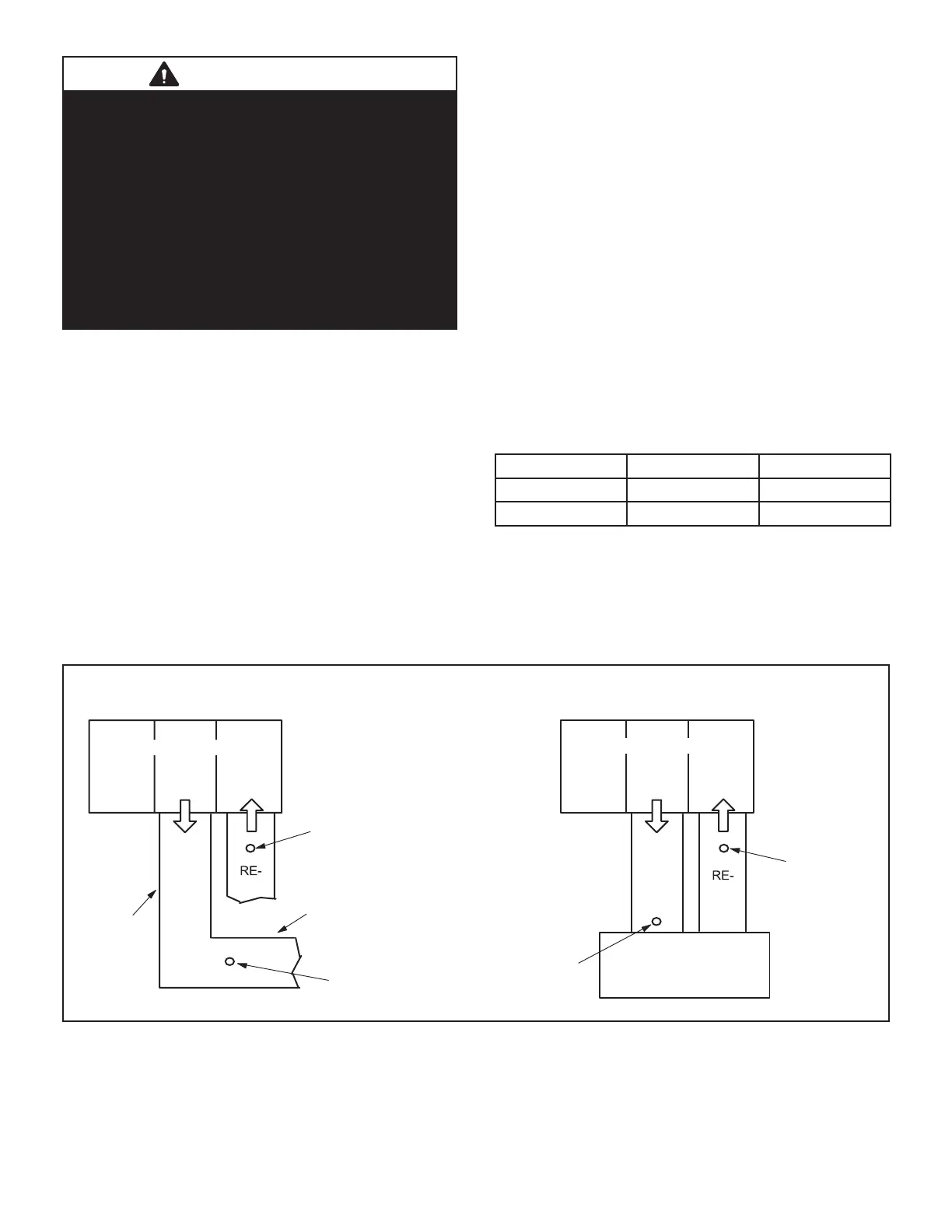
LOCATION OF STATIC PRESSURE READINGS
SUPPLY AIR
READING
LOCATION
SUPPLY
TURN
INSTALLATIONS WITH DUCTWORK
SUPPLY
TURN
INSTALLATIONS WITH CEILING DIFFUSERS
MAIN
DUCT RUN
FIRST BRANCH
OFF OF MAIN RUN
DIFFUSER
ROOFTOP UNIT
ROOFTOP UNIT
SUPPLY AIR
READING
LOCATION
RETURN AIR
READING LOCATION
RETURN AIR
READING
LOCATION
FIGURE 8

 Loading...

