24
11. Power and Communication Wiring for
Systems
CAUTION
Thisunit mustbeproperlygrounded and protectedbya
circuitbreaker.The groundwirefor theunitmust notbe
connectedtoagasorwaterpipe,alightningconductoror
atelephonegroundwire.
Do not connect power wires to the outdoor unit un-
til all other wiring and piping connections have been
completed.
Install all wiring at least 3 feet (1 m) away from televi-
sions, radios or other electronic devices in order to
avoid the possibility of interference with the unit op-
eration.
Do not install the unit near a lighting appliance that in-
cludes a ballast. The ballast may affect remote control
operation.
WARNING
Isolate the power supply before accessing unit electri-
cal terminals.
Install unit so that unit disconnect is accessible.
Follow all local and national codes, as well as this
installation instruction, during installation. Do NOT
overload electrical circuit, as this may lead to failure
andpossiblere.
Usespeciedwiringandcabletomakeelectricalcon-
nections. Clamp cables securely and make sure that
connections are tight to avoid strain on wiring. Inse-
cure wiring connections may result in equipment fail-
ureandriskofre.Wiringmustbeinstalledsothatall
cover plates can be securely closed.
IntheU.S.A.,wiringmustconformwithcurrentlocalcodes
and the current National Electric Code (NEC). In Canada,
wiringmustconformwithcurrentlocalcodesandthecurrent
CanadianElectricalCode(CEC).
Refer to unit nameplate for minimum circuit ampacity and
maximumover-currentprotectionsize.
• Allindoorunitsarepoweredbytheoutdoorunit.
• Makeallelectricalpowerwiringconnectionsatthe
outdoor unit.
• Sizeoutdoorunitpowerperlocalcodeandpower
requirements.
• Connectwiringbetweenindoorandoutdoorterminals.
• Refertounitnameplateforratedvoltage.
• Besuretoreattachallelectricalboxcoversafter
connectionsarecomplete.
• FollowNEC/CECstandardsandalllocalandstate
codesduringwiringinstallation.
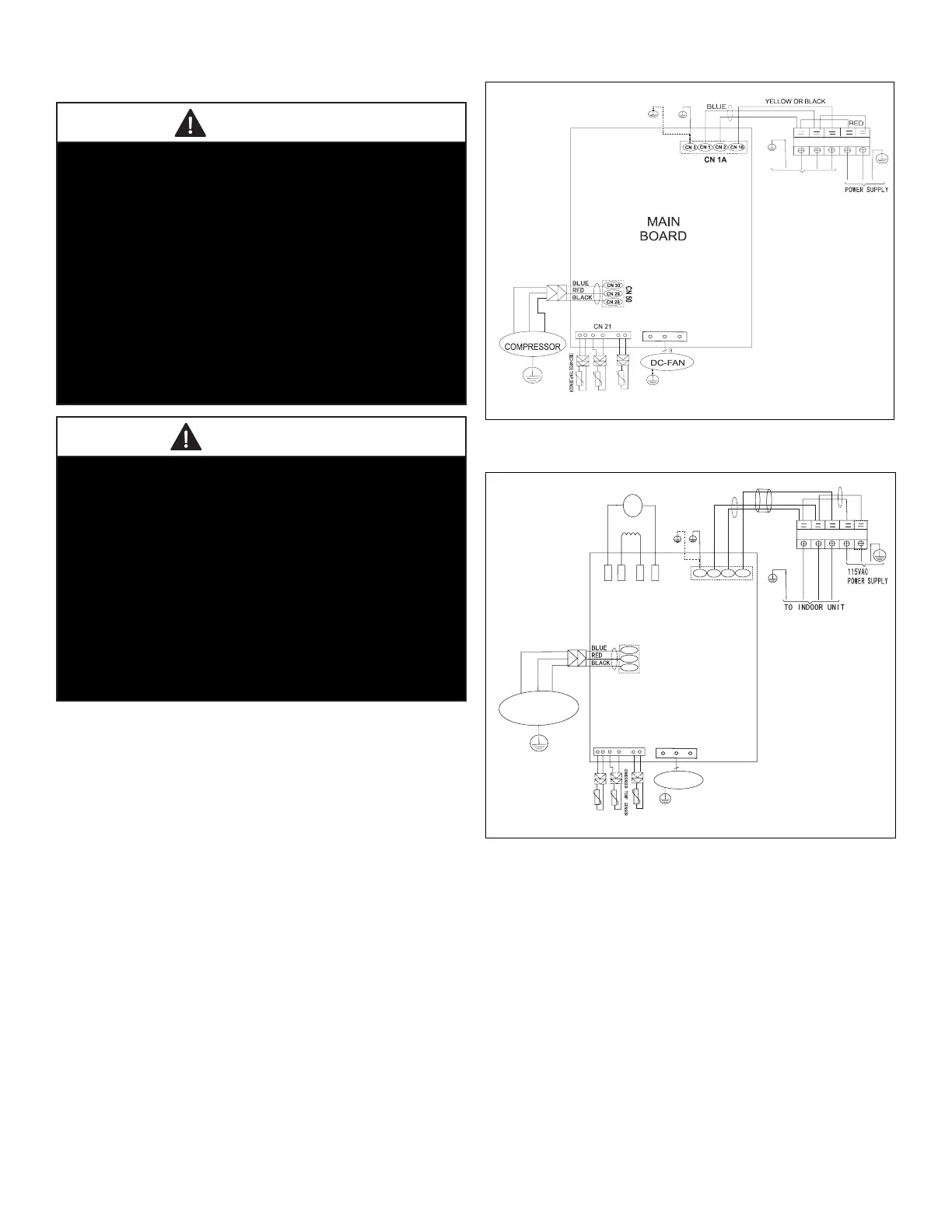
12. Outdoor Unit Diagrams
BROWN
3
2
L1
L2
BLACK
1
Y/G
AMBIENT TEMP. SENSOR
CONDENSER TEMP SENS OR.
Y/G
Y/G
Y/G
U
V
W
BLUE
RED
BLACK
Y/G
Y/G
Indoor Unit
T5
T3
T4
Figure 22. 09 and 12K - 208/230VAC Outdoor Unit
Wiring Diagram
COMPRESSOR
Y/G
DC-FAN
CN 7
3
B LUE
B R OWN
BLACK
3
2
L
N
R E D
B LUE
Y/G
1
Y/G
AMBIENT TEMP. SENSOR
DIS CHAR G E TEMP. SENS OR
CN 21
.
Y/G
Y/G
Y/G
CN4_1
CN4_2
CN4_3
CN4_4
REACTOR
CAPACITOR
BROWN
BROWN
BLACK
BLACK
BLACK
W
V
RED
BLUE
U
CN 1A
CN 3
CN 1
CN 2
CN 16
CN 50
CN 30
CN 29
CN 28
OUTDOOR
MAIN
PCB
T5 T3 T4
Figure 23. 12K - 115VAC Outdoor Unit Wiring
Diagram
 Loading...