25
DC-FAN
CN 414
3
AMBIENT TEMP. SENSOR
DISCHARGE TEMP. SENS OR
CN 17
.
Y/G
OUTDOOR
MAIN
PCB
BLUE
BROWN 1
BLACK 3
3
2
L1
L2
RED
BLUE L2
1
Y/G
Y/G
CN 3
Y/G
Y/G
COMPRESSOR
Y/G
U
V
W
BLUE
RED
BLACK
L1
L2
S
CN 6
CN 7
CN 8 CN 2
CN 21
W
V
U
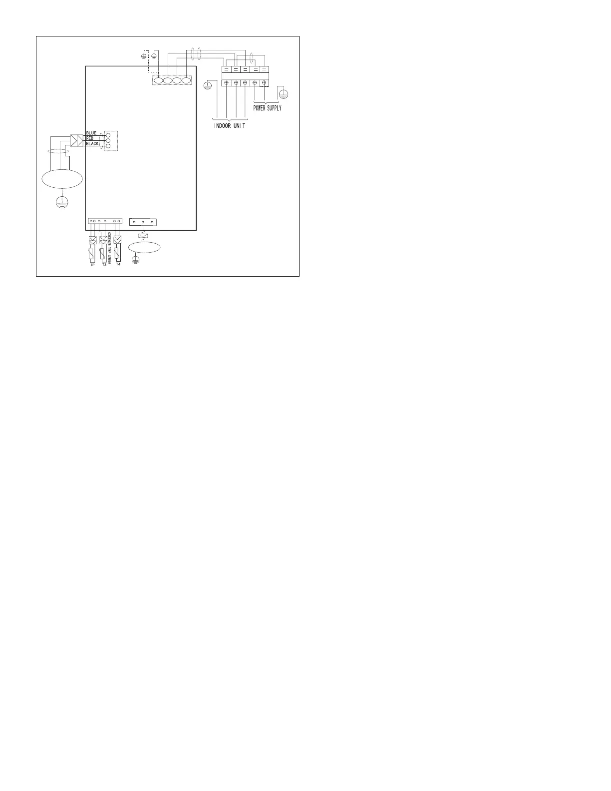
Figure 24. 18K and 24K 208/230VAC Outdoor Unit
Wiring Diagram
13. Installation Requirements
13.1. Gas Leak Check with Soap Water:
Apply soap water or a liquid neutral detergent on the
connectionswithasoftbrushtocheckforleakageinthepipe
connectingpoints.Ifbubblesemerge,thepipesareleaking.
13.2. Air and Moisture
Airandmoistureintherefrigerantsystemcausethefollowing
problems:
• Increasesinsystempressure
• Increasesinoperatingcurrent
• Decreasesincoolingandheatingefciency
• Blocksincapillarytubingcausedbymoistureinthe
refrigerantcircuitfreezing
• Corrosionofpartsintherefrigerantsystemcausedby
water
Theindoorunitsandthepipesbetweenindoorandoutdoor
unitsmustbetestedforleakagesandevacuatedtoremove
gasandmoisturefromthesystem.
13.3. Air Purging using a Vacuum Pump
• Completelytightenthearenutsontheindoorand
outdoorunits.Conrmthatboththetwo-wayandthree-
wayvalvesaresettotheclosedposition.
• Connectthechargehosewiththepushpinofthe
HandleLotothethree-wayvalvegasserviceport.
• ConnectthechargehoseoftheHandleHitothe
vacuumpump.
• FullyopentheHandleLoofthemanifoldvalve.
• Turnonthevacuumpumptobeginevacuation.
• Conducta30-minuteevacuation.Checkwhether
thecompoundmeterindicates-0.1Mpa(14.5Psi).If
themeterdoesnotindicate-0.1Mpa(14.5Psi)after
30minuteshaselapsed,continueevacuationfor20
moreminutes.Ifthepressuredoesnotreach-0.1Mpa
(14.5Psi)after50minuteshaselapsed,checkifthere
areanyleaks.
• FullyclosetheHandleLovalveofthemanifoldvalve
andturnoffthevacuumpump.Afterveminutes,
conrmthatthegaugeneedleisnotmoving.
• Turnthearenutonthethree-wayvalve45°counter-
clockwisefor6-7seconds.Oncegasbeginstocome
out,tightenthearenut.Makesurethepressure
displayonthepressureindicatorishigherthan
atmosphericpressure.Thenremovethechargehose
fromthethree-wayvalve.
• Fullyopenthetwo-wayandthree-wayvalvesand
securelytightenthecaponthethree-wayvalve.
13.4. Adding Refrigerant if Pipe Length
Exceeds Charge Less Pipe Length
Connectthechargehosetothechargingcylinderandopen
the two-way and three-way valves. With the charge hose
youdisconnectedfromthevacuumpump,connectittothe
valveatthebottomofthecylinder.
IftherefrigerantisR-410A,placethecylinderbottom-upto
ensureliquidchargingispossible.
• Purgetheairfromthechargehose.
• Openthevalveatthebottomofthecylinderandpress
thecheckvalveonthechargeset(becarefulofthe
liquidrefrigerant).
• Placethechargingcylinderontotheelectronicscale
andrecordtheweight.
• Turnontheairconditionerincoolingmode.
• Openthevalves(Lowside)onthechargeset.Charge
thesystemwithliquidrefrigerant.
• Whentheelectronicscaledisplaystheproperweight
(refertothetable),disconnectthechargehosefrom
thethree-wayvalve’sserviceportimmediatelyandturn
offtheairconditionerbeforedisconnectingthehose.
• MountthevalvestemcapsandtheserviceportUse
atorquewrenchtotightentheserviceportcaptoa
torqueof18N.m(13.27ft·lbs).
• Besuretocheckforgasleaks.
13.5. Add Refrigerant after Long-Term
System Operation
• Connectthechargehosetothethree-wayserviceport
andopenthetwo-wayandthree-wayvalve.
• Connectthechargehosetothevalveatthebottom
ofthecylinder.IftherefrigerantisR-410A,placethe
cylinderbottom-uptoensureliquidcharge.
 Loading...