EasyManua.ls Logo

Lennox MLA Series User Manual

Lennox MLA Series
20 pages
To Next Page IconTo Next Page
To Previous Page IconTo Previous Page
Page #9 background image
9
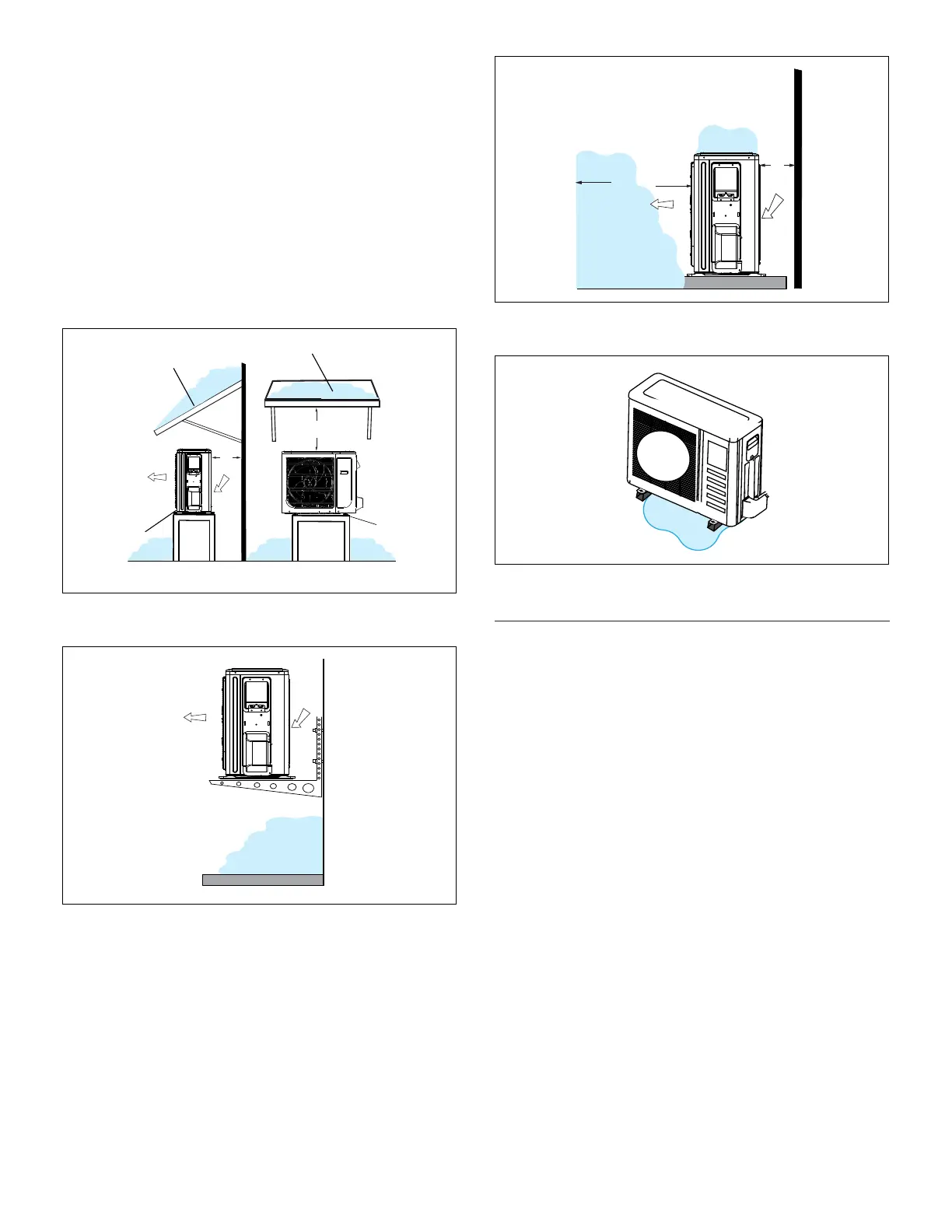
or into unit. Construct a canopy as illustrated in “Fig-
ure 7. Outdoor Unit on Pedestal (Stand) and Protec-
tive Canopy”.
The unit base should be elevated above the depth of
average snows as illustrated in “Figure 8. Outdoor Unit
on Brackets above Snow Line”.
In heavy snow areas, do not place the unit where drift-
ing will occur as illustrated in “Figure 9. Outdoor Unit
Air Flow Obstructed by Snow” on page 9.
Carefully consider how to manage defrost water dis-
posal to prevent ice from blocking walkways or creat-
ing a safety hazard near the outdoor unit as illustrat-
ed in “Figure 10. Avoid Defrost Water Ice Hazard” on
page 9.
12 in
305 mm
Air Inlet
Air Outlet
24 in
610 mm
Side View
Front View
Protective canopy
Protective canopy
Pedestal
(stand)
Pedestal
(stand)
Figure 7. Outdoor Unit on Pedestal (Stand) and
Protective Canopy
Air Inlet
Air Outlet
Figure 8. Outdoor Unit on Brackets above Snow
Line
Air Outlet
Air Inlet
12 in
305 mm
79 in
2007 mm
Figure 9. Outdoor Unit Air Flow Obstructed by
Snow
Figure 10. Avoid Defrost Water Ice Hazard
Prevailing Winds
Normally wind bafes are not required for a outdoor unit.
However, in order to maximize reliability and performance,
the following best practices should be followed.
If unit coil cannot be installed away from prevailing winter
winds, some method of protecting the coil is recommended.
However, minimum clearances as reference in “Figure 3.
Outdoor Unit Clearances - Inches (mm)” on page 6
must be observed at all times.
Common application examples are:
When prevailing winds are from the air inlet side, then
position the wind barrier a minimum of 12 inches (305
mm) from the unit as illustrated in “Figure 11. Wind
Barrier”.
When prevailing wind is into the discharge side, then
position the wind barrier a minimum 79 inches (2007
mm) from the front of the unit as illustrated in “Figure
11. Wind Barrier”.
Outdoor unit can be installed in a dog house style
shelter as illustrated in “Figure 12. Dog House-Style
Shelter”.
a roof overhang as illustrated in “Figure 13. Unit in-
stalled in Alcove”.
Question and Answer IconNeed help?

Do you have a question about the Lennox MLA Series and is the answer not in the manual?

Lennox MLA Series Specifications

General IconGeneral
BrandLennox
ModelMLA Series
CategoryAir Conditioner
LanguageEnglish

Summary

General Installation Overview

Use of Mini-Split System During Construction

Guidance on operating mini-split systems during construction phases to prevent damage.

Included Parts and Accessories

Optional Accessories

List of optional components available for the system.

Indoor / Outdoor Unit Match-Ups

Information on compatible indoor and outdoor unit combinations.

Model Number Identification

Typical Single-Zone System Components

System Dimensions

System Clearances

Torque Requirements for Caps and Fasteners

Indoor Unit Installation

Unit Placement Considerations

Guidelines for selecting the optimal location for the indoor unit, avoiding hazards.

Floor Installation

Instructions for mounting the indoor unit on the floor, ensuring stability and clearances.

Indoor Unit Condensate Piping Connections

Outdoor Unit Installation

Placement Considerations

Factors to consider when positioning the outdoor unit to avoid noise and environmental issues.

Direct Sunlight, Rain, Snow and Ice Protection

Recommendations for protecting the outdoor unit from direct sun, rain, snow, and ice.

Prevailing Winds Protection

Buried Refrigerant Pipe Protection

Securing the Outdoor Unit

Slab or Roof Mounting

Guidelines for securing the outdoor unit onto a slab or roof structure.

Refrigerant Piping Connections

Making Connections (Male to Female Connection)

Step-by-step guide for connecting refrigerant lines using flare fittings.

Flare Nut Torque Recommendations

Specifications for tightening flare nuts to ensure leak-free refrigerant connections.

Leak Test and Evacuation

Leak Test Procedure

Procedure for testing the refrigerant system for leaks using nitrogen.

Triple Evacuation Procedure

Multi-stage process to evacuate the system to the required vacuum level.

Wiring Connections

Outdoor Unit Wiring

Instructions for making electrical connections to the outdoor unit.

Indoor Unit Wiring

Instructions for making electrical connections to the indoor unit.

Single Zone Installation Wiring Requirements

Function of Switches

Auto-Restart Function Setup

How to configure the auto-restart function using DIP switches.

Down Louver Setting

How to set the down louver position using DIP switches.

Unit Start-Up

Adding Refrigerant for Longer Line Set

Troubleshooting

Test Run

Procedure for performing a test run to verify system functionality.

Dry Mode Operation (Dehumidification)

User Guide Features

Default Settings

Describes the system's default settings after a power failure.

Auto-Restart

Explains how the system restarts after a power interruption.

Louver Angle Memory Function

Details the function that remembers the louver position.

Refrigerant Leak Detection System

How the system indicates a refrigerant leak.

Manual Operations

How to operate the unit using the indoor unit's control panel.

Adjusting Airflow Direction

How to Clean the Air Filter

Error Codes

Optional Programmable Wired Controller

Programmable Controller Connection

Instructions for connecting the programmable wired controller.

Non-Programmable Controller Compatibility

Information on the incompatibility with a non-programmable wired controller.

Related product manuals