Page 10
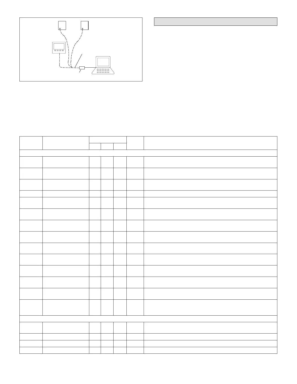
NTC
NCP
PC
NTC
CONNECT FIELD−PROVIDED
PHONE CORD TO PHONE
JACK ON NTC OR NCP
PC TO L CONNECTION
CONVERTER
Figure 12. L Connection Converter
Connect the converter to either the NTC or the Network
Control Panel (NCP).
Reset NTC Parameters to Default
Restore the NTC controller parameters to default settings
as follows:
1. Disconnect power to NTC (P176).
2. Move all DIP switches on the Unit Address DIP switch
to OFF.
3. Move all switches on the Conguration DIP switch,
except for switch 7, to OFF.
4. Connect controller power (P176). The heartbeat LED
will cycle red, green, and off.
5. Press the pushbutton; the heartbeat LED will display
red.
6. Wait until the LED cycles red, green, and off. Return
Unit Address and Conguration DIP switches to the
previous position.
7. Hold the pushbutton to reset controller to normal
operation.
Table 10. NTC Controller Parameters
Control
No
Parameter Name
Control Value
Units Description
Min Def Max
BLOCK 1 HEATING PARAMETERS
A1.01
Heating Backup
Setpoint
40 70 95 Deg.F
Backup heating setpoint. Used if the communications link is lost (after 5
mins.) A1.10 <=A2.01−A4.03
A1.02
Stage 1 Heating
Differential
0 0.5 3 Deg. F Stage 1 heating differential. A1.02<=A1.03
A1.03
Stage 2 Heating
Differential
0 1 3 Deg. F Stage 2 heating differential. A1.03>=A1.02
A1.04 Heating Deadband 1 1 3.75 Deg. F Heating stage deadband. A1.04 <=A4.03−A2.05
A1.05
Upper Stage Heating
Latch Option
0 0 1 Option Option used to hold upper stage on until temperature reaches setpoint.
A1.06 Heating Stage−Up Timer 0 0 60 Min.
Optional timer used to call the upper demand if the lower stage runs for this
time. Disabled if set to “0”.
A1.07
Heating Stage Down
Timer
0 0 30 Min.
Optional time delay that occurs before a lower stage turns off following a
higher stage termination.
A1.08
Occupied Warm−Up
Delay
0 30 120 Min. The delay on OCP output for rst heating demand in occupied period.
A1.09
Heating Return Air Limit
Option
0 0 1 Option Heating return air limit option enable.
A1.10
Heating Return Air
Lim- it
60 85 100 Deg. F
Return air temp. limit. Heating outputs off if return air temp. exceeds limit.
ECTO A1.09 must be set to 1 to enable this limit.
A1.11
Heating Blower On
Delay
0 0 60 Sec. Length of time before the blower turns on after a heating demand.
A1.12
Heating Blower Off
Delay
0 0 300 Sec. The time the blower stays on after the heating demand is lost.
A1.13
HP Supp. Heat
Lockout Temp.
20 40 60 Deg.F
Outdoor temperature setpoint for lockout of supplemental heat on heat
pump units. Outdoor sensor required (RT17).
A1.14
Heat Pump Compr. Low
Temp. Lockout
−30 −30 50 Deg. F
Heat pump low ambient compressor lockout temperature. A value of − 31°F
will disable the low ambient lockout function. Outdoor sensor required
(RT17).
BLOCK 2 COOLING PARAMETERS
A2.01
Cooling Backup
Setpoint
40 75 95 Deg.F
Backup cooling setpoint. Used if the communications link is lost (after
5mins.) A2.01>= A1.01+A4.03
A2.02 Y1 Cooling Differential 0 0.5 4 Deg. F Y1 cooling differential. A2.02<= A2.03
A2.03 Y2 Cooling Differential 0 1 4 Deg. F Y2 cooling differential. A2.03>= A2.02 and <=A2.04
A2.04 Y3 Cooling Differential 0 1.5 4 Deg.F Y3 cooling differential. A2.04>= A2.04