Page 4
3
4
5
6
7
8
2
1
ype Of Unit
Number of
Cooling S tages
Number of
Should be
OFF
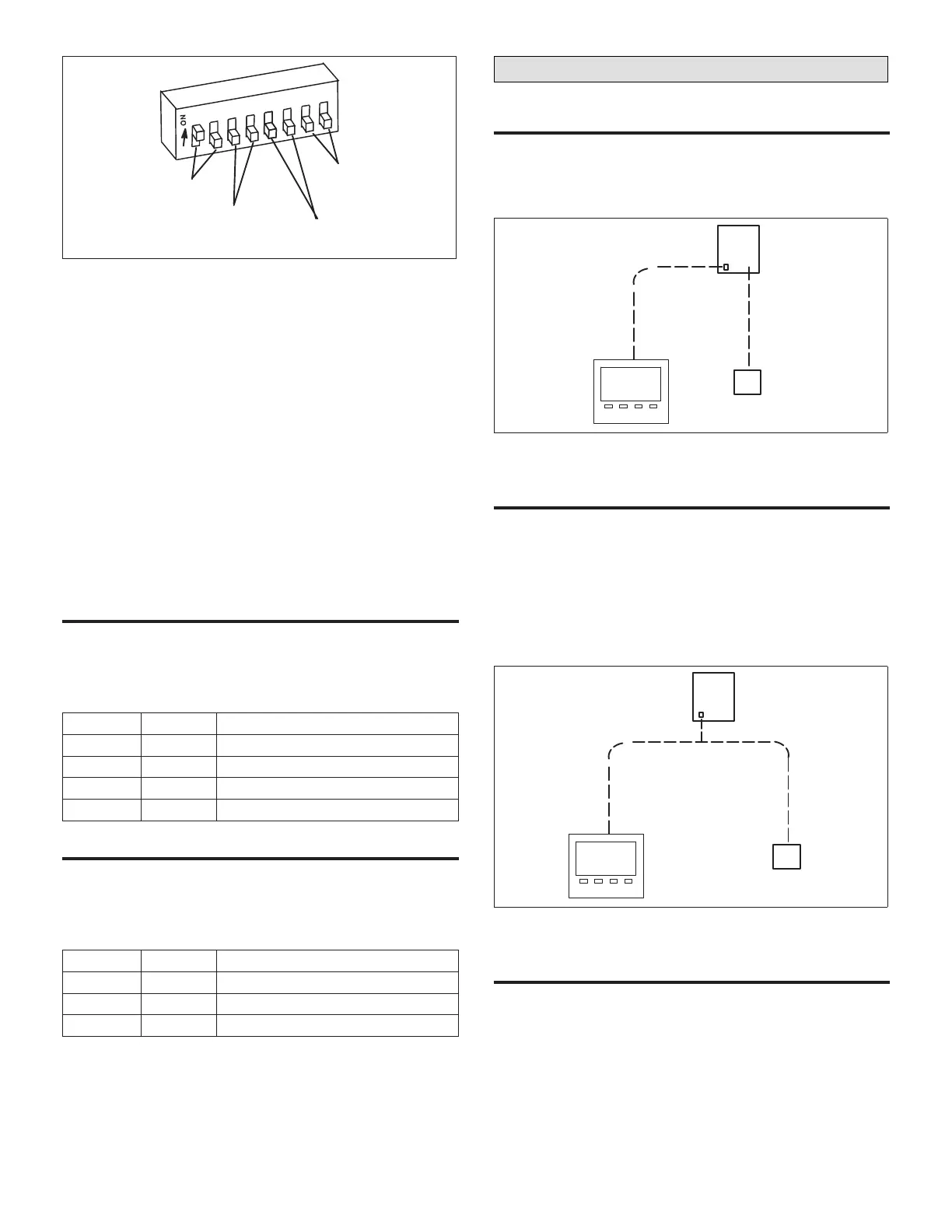
Figure 5. Conguration DIP Switches
• Electric Heat / Electric Cool Units - Standard electric
heat / electric cool unit.
• Heat Pump Type 1 Units - Heat pump units which
internally energize the reversing valve. Lennox
commercial heat pumps operate in this manner.
• Heat Pump Type 2 Units - Heat pumps units which
require a thermostat signal to energize the reversing
valve. Most residential heat pumps operate in this
manner. Connect Lennox residential heat pumps to O”
output.
• Electric Cool / Gas Heat Units - Standard electric cool
/ gas heat unit.
• Air Handling Only Units - Switches 1 and 2 may be
set in any position for air handling units, but switches 3
through 6 must be set to OFF.
Number Of COOliNg StageS − SwitCheS 3 aNd 4
Set switches 3 and 4 to identify the number of cooling
stages. See the following table and “Figure 5. Conguration
DIP Switches”.
Table 4. Cooling Stages Switches
Switch 3 Switch 4 Number of Cooling Stages
OFF OFF None
ON OFF 1 Stage
OFF ON 2 Stages
ON ON 3 Stages
Number Of heatiNg StageS − SwitCheS 5 aNd 6
Set switches 5 and 6 to identify the number of heating
stages. See the following table and “Figure 5. Conguration
DIP Switches”.
Table 5. Heating Stages Switches
Switch 3 Switch 4 Number of Heating Stages
OFF OFF None
ON OFF 1 Stage
OFF ON 2 Stages
Local or Remote System Mode
loCal sensoR
NTC ECTO A4.07 is factory−set to option 0 (local). In this
system mode, the NTC will operate the unit based on input
from a local sensor. A two−wire, thermistor− type sensor is
wired to NTC P178 terminals 1 and 2.r
NCP
NTC
Local Sensor
SysBus
Figure 6. Local Sensor
RemoTe sensoR
If an L Connection communication−ready sensor, such as
the Comfort Sensor, is specied, ECTO A4.07 must be set
to option 1 (remote). In this system mode, the NTC will
operate the unit based on input from the Comfort Sensor.
Connect the Comfort Sensor to the L Connection SysBus.
NOTE: The Comfort Sensor−Zoning is also an L Connection
communication−ready sensor but is designed for
use in L Connection zoning applications.
NCP
Comfort Sensor
SysBus SysBus
Figure 7. Remote Sensor
SeNSOr baCk−up OperatiON
Optional return air sensor RT16 is used as a back−up if
the A2 or A74 sensor fails or is disconnected. If RT16 fails
or is not installed, unit heating and cooling operation stops.
NOTE: The RT16 has a lower resolution than the A2 local
sensor or the A74 remote sensor and should only
be used as back−up.