Page 7
110
111
112
113
114
115
109
108
107
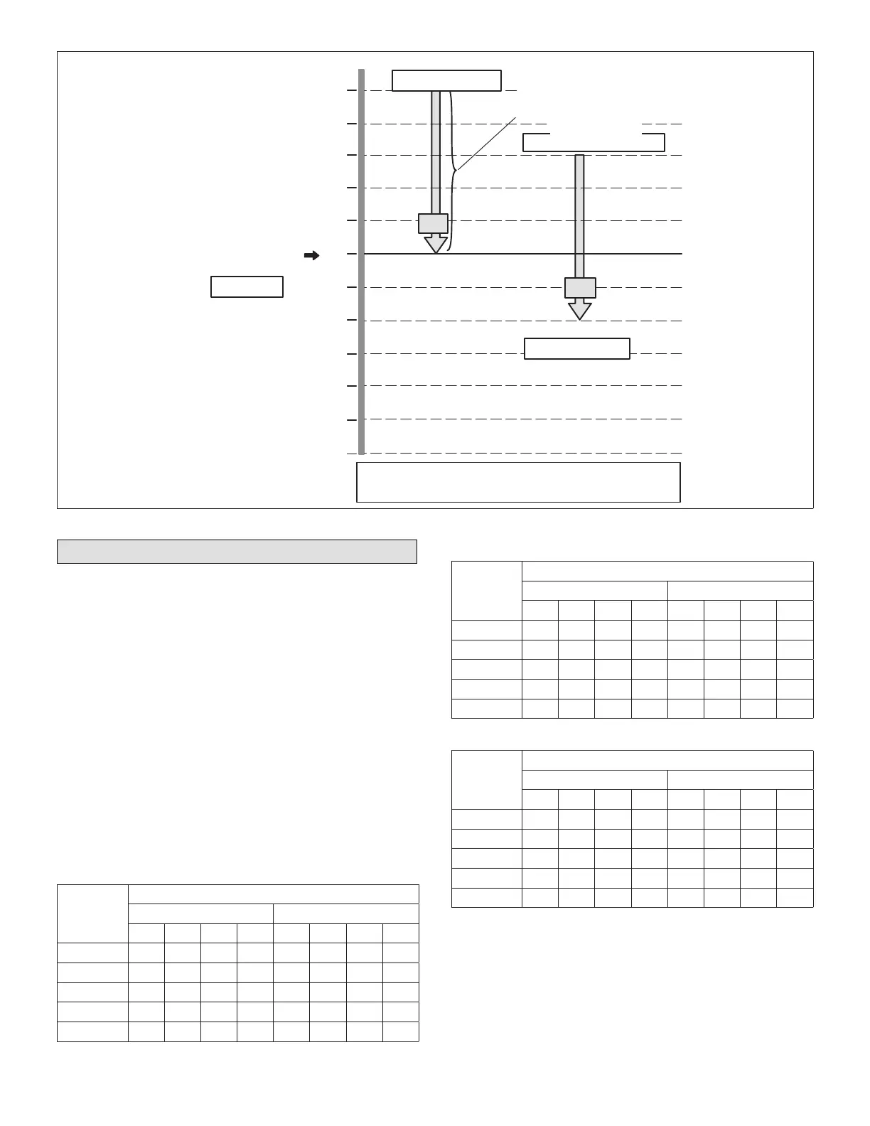
110°F
Default Occupied
DACH Setpoint
H1
ON
OFF
110°F + 5°F
ECTO A4.08 + A4.09
A4.10 DACH S tage−Up Delay 3 minutes
A4.11DACH S tage−Down Delay 2 minutes
Compressor Minimum Run Times Apply
106
105
104
5°F
DACH Deadband
(All Stages Same Setting)
H2
ON
OFF
110°F − 2°F Di
ECTO A4.08 − A4.12
ECTO A4.09 − A4.12 + A4.09
ECTO A4.08
H1=Heating Stage 1
H2=Heating Stage 2
110°F − 2°F + 5 °F
Figure 10. Discharge Air Control Heating (DACH) Stages − Default Values Shown
Digital Outputs − P181 and P182
Each output is a fused, dry contact and is rated for 24VAC,
two amp maximum.
Refer to the appropriate unit in tables 6 through 9 to
determine the digital output resulting at different thermostat
inputs. The appropriate digital output LED will be energized
at the same time. The output can also be read with a
voltmeter at P181 and P182. Conguration DIP switches
should be set as shown in tables 3 through 5 for each
type of unit. When an air handling unit is installed, the “ G”
output is energized during the occupied time period. See
system parameter A4.01.
All output tables show the G blower output during the
unoccupied time period. During the occupied time period
blower operation will be continuous. If A4.01 system
parameter is changed to option 0, the blower will operate
as shown in tables regardless of time period.
Output tables do not show blower on/off delays.
Table 6. Electric Cool / Gas Heat Units
Thermostat
Demand
NTC Digital Output
P181 P182
Y1 Y2 Y3 W1 W2 0 B G
1st Cool ON OFF OFF OFF OFF N/A N/A ON
2nd Cool ON ON OFF OFF OFF N/A N/A ON
3rd Cool ON ON ON OFF OFF N/A N/A ON
Low Heat OFF OFF OFF ON OFF N/A N/A OFF
High Heat OFF OFF OFF ON ON N/A N/A OFF
Table 7. Electric Cool / Electric Heat Units
Thermostat
Demand
NTC Digital Output
P181 P182
Y1 Y2 Y3 W1 W2 0 B G
1st Cool ON OFF OFF OFF OFF N/A N/A ON
2nd Cool ON ON OFF OFF OFF N/A N/A ON
3rd Cool ON ON ON OFF OFF N/A N/A ON
Low Heat OFF OFF OFF ON OFF N/A N/A ON
High Heat OFF OFF OFF ON ON N/A N/A ON
Table 8. Heat Pump Units Type 1
Thermostat
Demand
NTC Digital Output
P181 P182
Y1 Y2 Y3 W1 W2 0 B G
1st Cool ON OFF OFF OFF OFF N/A N/A ON
2nd Cool ON ON OFF OFF OFF N/A N/A ON
3rd Cool ON ON ON OFF OFF N/A N/A ON
Low Heat OFF OFF OFF ON OFF N/A N/A OFF
High Heat OFF OFF OFF ON ON N/A N/A OFF