Page 3
CommeRCial spliT sysTems
1. Disconnect all electrical power to the unit.
2. Mount the enclosure in a convenient location near the
control box.
3. Secure the NTC1 baseplate to the enclosure using the
screws provided.
IMPORTANT
Do not remove the NTC1−1 baseplate.
BASEPLATE
MOUNTING
HOLES IN
EACH
CORNER
Figure 2. NTC1 Network Thermostat Controller
(A113) Mounting Hole Locations
Heartbeat LED
See following table for LED function and “Figure 1. NTC1
Network Thermostat Controller” on page 2 for location.
Table 1. Heartbeat LED
LED Indicates
Green on for 1 second, off for 1
second
Normal operation.
Green on for 3 seconds, off for 3
seconds
Delay initiated
Red on for 1 second, off for 1
second
No run lockout
Pushbutton
A short push of the pushbutton by−passes on/off delays.
The heartbeat LED indicates when the delay is initiated.
See “Table 1. Heartbeat LED” to reset the controller, press
and hold the pushbutton.
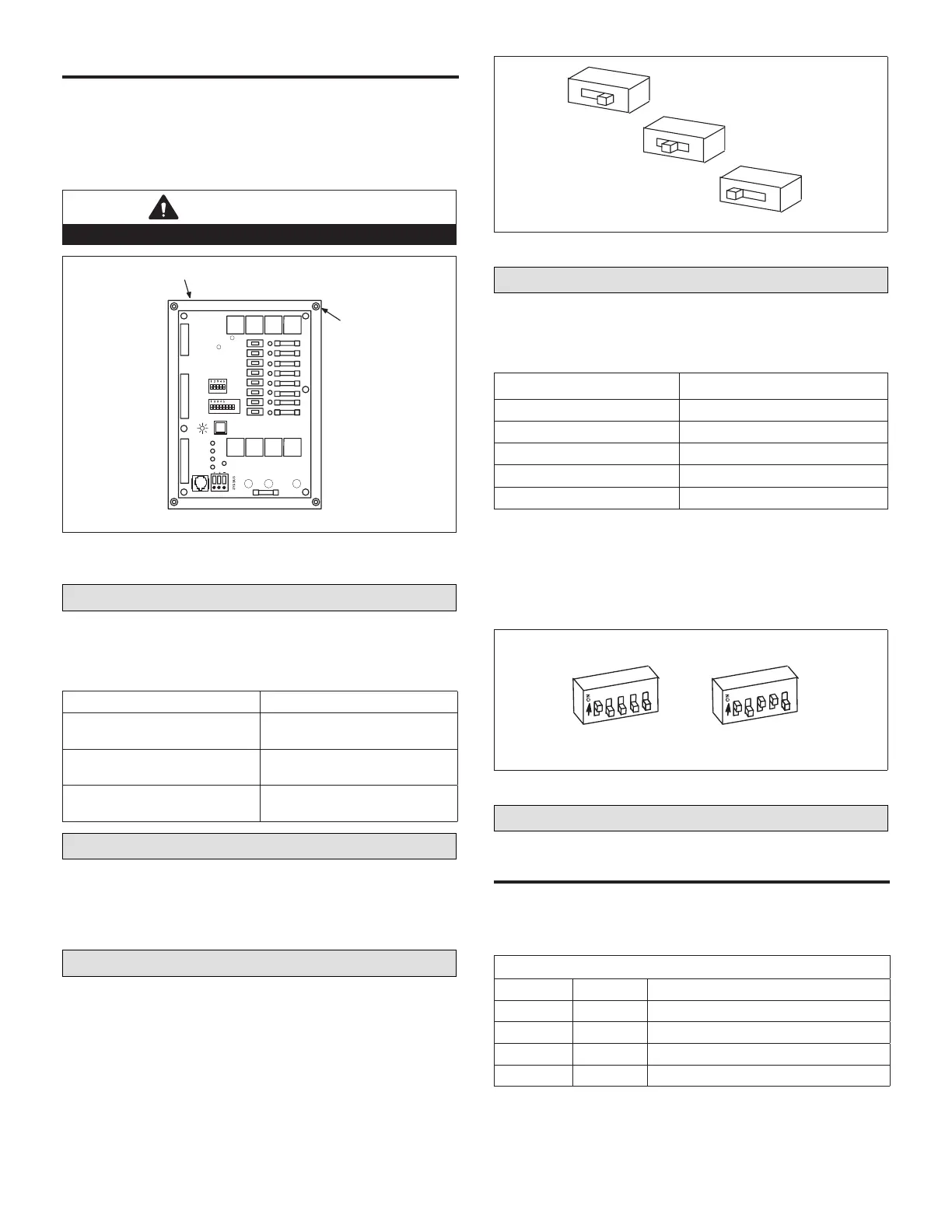
Manual Output Test Switches
Manual switches simulate a thermostat demand to conrm
proper unit operation. Switches have three positions: on,
off, and auto. Place switches in the auto position for normal
unit operation. Place switch in the off position to disable
the output and in the on position to test unit function. See
the following gure.
OFF
ON
AUTO
Figure 3. Manual Output Test Switches
Unit Address DIP Switches
See “Figure 1. NTC1 Network Thermostat Controller” on
page 2 for DIP switch location.
Table 2. Address Values
DIP Switch Label Value
1 1
2 2
3 4
4 8
5 16
• Assign a unique address for each building controller
attached to the network.
• The address of each building controller will be 100 plus
the address set by the switches. For two examples,
see the following gure. Up to 31 unique addresses are
available.
Example of Address 101
Example for Address 113
DIP Address 1 + 3 + 4 = 113
1
2
3
4
5
1
2
3
4
5
Figure 4. Unit Address Dip Switches
Conguration DIP Switches
Types of UniTs - swiTChes 1 and 2
Set conguration DIP switches 1 and 2 to identify the type
of unit. See the following table and gure.
NOTE: Switches 7 and 8 should be OFF.
Table 3. Conguration DIP Switches
Switch 1 Switch 2 Type of Unit
OFF OFF Electric Cool/Electric Heat
ON OFF Heat Pump Type 1 Unit
OFF ON Heat Pump Type 2 Unit
ON ON Electric Cool/Gas Heat