Page 45
High Efficiency Energence A Box Units with Smart Airflow™ (Advance Airflow) Applications that have Smart
Airflow™ option installed and with successful blower calibration, will run the blower at a calculated percent output to
deliver the airflow as set by the installer. The table below shows the default Airflow set points parameter. Parameter
18 by default is 0 but needs to be set to a valid value during installation.
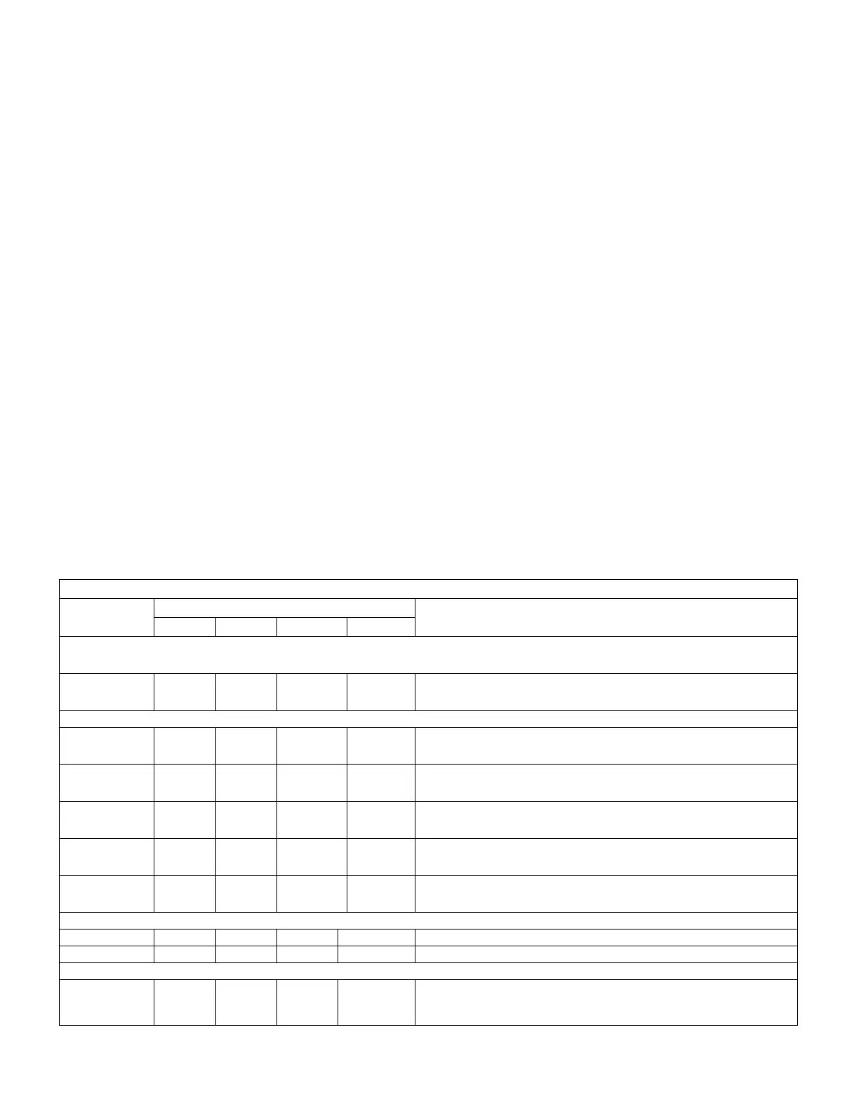
Table 35. High Efficiency Factory Settings (CFM) A Box Smart Airflow™ (3 to 5ton Units)
Operation
3 ton
(in CFM)
4 ton
(in CFM)
5 ton
(in CFM)
Parameter Value
(in CFM/ton)*
Parameter
Value
(in counts)
Parameter
Cooling low, Free cooling low 780 1040 1300 260 130 12
Cooling high, Free cooling high 1080 1440 1800 360 180 14
Heating 1200 1600 2000 400 200 13
Ventilation 0 0 0 0 0 18
Smoke alarm modes 1200 1600 2000 400 200 12
Minimum Outdoor Airflow 120 160 200 40 40 237
* Setting in CFM = tonnage of the unit multiplied by Parameter value in CFM/ton.
Standard Efficiency Energence A Box Unit with a BeltDrive TwoSpeed Motor. The speed is not parameter
selectable. During first stage cooling blower is at low speed, while blower runs at high speed in heating, second stage
cooling and smoke alarm (if configured), Ventilation may use low or high speed blower.
9.3.2. B Box (7.5 – 12.5 ton units)
Energence B Box 7.5 to 12.5ton MSAV units use direct driven blower (ultrahigh efficiency units only) or belt driven blower
with Variable Frequency Drive (VFD). Units have two compressors and on ultra high efficiency units they are set for tandem
operation. The actual blower speed and CFM delivered will depend on the flow restriction as well as the percent output. The
blower output for each mode of operation has been factory set, but it will need to be adjusted during test & balance on the
installed ductwork and the air delivery required for the application. The table below shows the default blower outputs
parameters as well as options for minimum damper position.
Refer to table 19 and 20 in Section 6.6 for detailed information on system operation in various configurations and operating
modes.
Table 36. B Box (2Compressor) Units with Multi-Stage Air Volume (7.5 12.5 ton)
Parameter
Capacity (tonnage)
Description
7.5 8.5 10 12.5
Note: Any changes to Smoke CFM setting must be adjusted before the other CFM settings.
Use SETTINGS > RTU OPTIONS > EDIT PARAMETERS
12
3000
CFM
3400
CFM
4000
CFM
5000
CFM
Blower CFM during smoke detection.
SETUP > TEST & BALANCE (can also use SETTINGS > RTU OPTIONS > BLOWER > SPEEDS)
13
3000
CFM
3400
CFM
4000
CFM
5000
CFM Blower CFM during heating.
14
2700
CFM
2200
CFM
3600
CFM
4500
CFM Blower CFM during high speed (2 compressors) cooling.
17
1950
CFM
3050
CFM
2600
CFM
3250
CFM
Blower CFM during low speed (1 compressor) and free cooling.
18
3000
CFM
3400
CFM
4000
CFM
5000
CFM Blower CFM during ventilation.
19
1195
RPM
N/A
1425
RPM
1655
RPM
Blower RPM for max CFM (applicable only to unit with blower direct drive)
SETUP > TEST & BALANCE (can also use SETTINGS > RTU OPTIONS > DAMPER)
9 0% 0% 0% 0% Damper min. position during LOW blower operation.
132 0% 0% 0% 0% Damper min. position during HIGH blower operation.
SETTINGS > RTU OPTIONS > EDIT PARAMETERS
29 101% 101% 101% 101%
Damper minimum position during G blower operation. (Setting parameter
29 to “101” disables parameter 29 and passes control to parameter 9 or
132)