Page 47
9.4.2. Analog Output Control
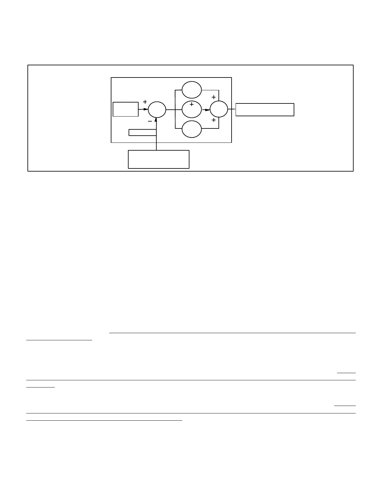
The analog output on the M3 Unit Controller (P2594) is set to closed loop PID or staged control when configured for
Constant Air Volume bypass damper (Configuration ID 2, position 7 must be set to Y). The closed loop PID method used by
the M3 Unit Controller has three constants manual resets; proportional (P), integral (I) and derivative (D) as shown in figure
1. The PID control constants, as well as the output values for minimum and maximum, may be adjusted if necessary.
M3 Unit
Controller
Static
Pres. SP
P Gain
I Gain
∑
∑
Static Pres. Sensor
(A30 P267−7
Feedback
D Gain
Bypass Damper
Figure 12. PID Operation Diagram for CAVB Air Delivery
Table 40. Summary of PID Constants Parameters
CAVB Air Delivery PID Constants
No. Screen Name Min Default Max Units Description
41 BLOWER MANUAL RESET 20.0 52.0 100.0 % Manual reset value.
31 BLOWER PID P CONST 0 17 127 Counts CAVB supply PID Proportional constant.
32 BLOWER PID i CONST 0 12 127 Counts CAVB supply PID Integral constant.
33 BLOWER PID D CONST 0 0 127 Counts CAVB supply PID derivative constant.
9.4.2.1. Blower Manual Reset — Parameter 41
Blower Manual Reset is used when the output values for PID P, I, and D constant values are all set to 0 (OFF). This is the
approximate output expected which allows quicker settling at set point. On Constant Air Volume units with bypass damper,
this is also the damper position when blower is off. Blower Manual Reset can be adjusted between 20 to 100%. Default
setting is 52%.
9.4.2.2. Blower Proportional Constant (P) — Parameter 31
To handle the present, this is the value of the “gain' that is multiplied times the error. The error is the difference between the
output and the set point. A large value of “P" will cause the output to reach the set point faster, however, this faster rate can
cause the output to overshoot the set point. On the other hand, a low value of “P" will reduce overshoot, but will cause the
output reaction to be too slow. The “P"constant parameter value can be adjusted between 0 –127 with 0 being off and 127
being the highest value.
9.4.2.3. Blower Integral Constant (I) — Parameter 32
To handle the past, this gain is proportional to the amount of time that the error is present. This gain tries to integrate out any
offset. A high value of “I" can provide fast correction but can cause overshoot and ringing. The “I' gain should be set to the
lowest value possible that corrects the offset. “I" can be adjusted between 0127 with 127 being the lowest value. The “I"
constant parameter value is inverted. A value of 0 turns the integral factor off. A value of 127 is the minimum and 1 is the
maximum.
9.4.2.4. Blower Derivative Constant (D) — Parameter 33
To handle the future, this gain is proportional to the rate of change of the error and provides a damping factor. The “D"
constant parameter value can be adjusted between 0 127 with 0 being off and 127 being the highest value. Most M3 Unit
Controller applications do not require using any “D" gain.