Page 79
Table 56. Exhaust Fan Parameters
Control Parameter Control Value
Units Description
No Screen Name Parameter Short Description Min. Default Max.
215 EXH FN STG1 DAMP SP
Exhaust Fan Stage 1 Damper
Set Point
0.0 50.0 100.0 %
Exhaust Fan stage 1 damper set
point.
216 EXH FN STG1 DAMP DB
Exhaust Fan Stage 1 Damper
Deadband
0.0
Check unit
parameter
label as
default may
be altered
af factory
test.
100.0 %
Exhaust Fan Stage 1 Damper
Deadband
219 EXH FN STG2 DAMP SP
Exhaust Fan Stage 2 Damper
Set Point
0.0 70.0 100.0 %
Exhaust Fan Stage 2 Damper Set
Point
220 EXH FN STG2 DAMP DB
Exhaust Fan Stage 2 Damper
Deadband
0.0 10.0 100.0 %
Exhaust Fan Stage 2 Damper
Deadband
223 EXH FAN STGUP DELAY Exhaust Fan Stage Up Delay 0 0 300 Sec Exhaust Fan Stage Up Delay
224 EXH FAN STGDWN DLAY Exhaust Fan Stage Down Delay 0 100 200 Sec
Stage 1 off-delay. (Only used for
2 stage operation)
19.1.4. Constant Air Volume Units in Single-Zone Applications with a Lennox Room Sensor (4-Heat /
4-Cool)
19.1.4.1. Unit Controller Operation
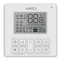
When using a Lennox room sensor with the M3 Unit Controller operating in room sensor mode, a packaged rooftop unit can
provide up to four stages each of mechanical heating and cooling operation. The room sensor provides space temperature
information to the M3 Unit Controller. The M3 Unit Controller houses all space temperature set points and controls all rooftop
unit staging and general operation functions. The M3 Unit Controller also determines unit error codes, provides diagnostic
information and maintains safe operation limits.
19.1.4.2. Ventilation Demand
When the M3 Unit Controller is in room sensor control mode, the user has several different ventilation sequence of operation
scenarios to choose from. The default mode causes the M3 Unit Controller to activate the supply fan when both a ventilation
and either heating or cooling demand are present. This occurs independent of receiving an occupied demand. The user can
change the default setting to allow the supply fan to run continuously when the M3 Unit Controller receives both a ventilation
and occupied demand. This is independent of a call for either heating or cooling. When the M3 Unit Controller receives a
ventilation demand and occupied demand is not present, the M3 Unit Controller will only activate the supply fan when it
receives either a heating or cooling demand.
19.1.4.3. Cooling Demand
The M3 Unit Controller directly monitors space temperature through the room sensor. Based on this information, the M3 Unit
Controller activates the different compressor stages to maintain the desired occupied space temperature set point.
Increasing compressor stages provides more cooling capacity while decreasing compressor stages provides less cooling
capacity. The M3 Unit Controller has direct control over the rooftop unit mechanical cooling staging operation. The user has
the option to configure the M3 Unit Controller so that if the room sensor fails, the M3 Unit Controller can use a backup
operation to control unit operation.
Energence units feature up to four separate compressors and refrigeration circuits that can provide up to four stages of
mechanical cooling operation.
For stage one operation, the M3 Unit Controller activates the first compressor (25% of total unit capacity). For stage two
operation, the M3 Unit Controller activates the second compressor (50% unit capacity). For stage three operation, the M3
Unit Controller activates the third compressor (75% total unit capacity). For stage four operation, the M3 Unit Controller
activates the fourth compressor (100% unit capacity). Depending on the room sensor configuration setting, occupants in the
space can change the set point. The M3 Unit Controller automatically recognizes this change and instructs the unit to
respond accordingly.
NOTE: Energence A Box MSAV models uses a two-step compressor (two speeds for cooling application) and must have
two-stage cooling inputs from a thermostat, third-party DDC control or third-party DDC electronic thermostat module
control.
19.1.4.4. Cooling Demand with Economizer
If the outdoor air is suitable for free cooling and the unit has an economizer, the M3 Unit Controller will open the economizer
and use fresh air for stage one cooling. For stage two cooling operation, the M3 Unit Controller activates the first
compressor. For stage three cooling operation, the M3 Unit Controller activates the second compressor. For stage four
cooling operation, the M3 Unit Controller activates the remaining compressors (number three and four). The M3 Unit
Controller has direct control over the rooftop unit mechanical cooling staging and economizer operation.

 Loading...
