18
(PQE)
(PQE)
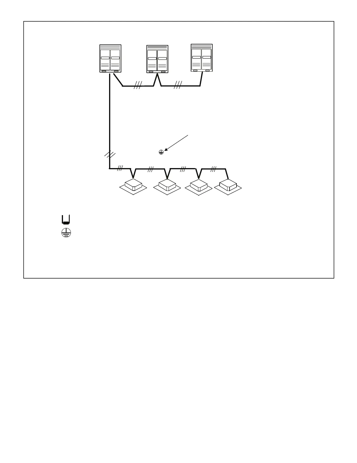
Ground cable shield
DO NOT connect to E
Outdoor unit
(main unit)
Outdoor unit
(sub1 unit)
Outdoor unit
(sub2 unit)
(H1 H2 E) (H1 H2 E) (H1 H2 E)
Install a terminating resistor at the last indoor unit terminals P and Q of the daisy
chain.
P Q
All shields of shielded cable connect to GROUND terminal,
not to terminal E.
18 GA., stranded, 3-conductor, shielded control wire (polarity sensitive).
Typical Wiring Diagram, NEC/CEC and Local Codes apply.
Figure 17. Typical Communication Wiring Diagram (VRF Heat Pump System)
NOTE – PQE Communication wiring is daisy-chained from the outdoor unit to each indoor unit in one continuous run.
 Loading...