5.Ensurethatthenewpowersupplyassemblyisthecorrectreplacement.
6.Installthenewpowersupplyassemblyintothechassissothatthescrewholesinthepowersupply
assemblyalignwiththoseinthechassis.
7.Installandtightenthefourscrewstosecurethepowersupplyassembly.
Note:UseonlyscrewsprovidedbyLenovo.
8.Connectthepowersupplyassemblycablestothesystemboardandeachofthedrives.
9.Securethepowersupplyassemblycableswiththecableclipsandtiesinthechassis.
Whattodonext:
•Toworkwithanotherpieceofhardware,gototheappropriatesection.
•Tocompletetheinstallationorreplacement,goto“Completingthepartsreplacement”onpage97.
Heatsinkandfanassembly
Attention:Donotopenyourcomputerorattemptanyrepairbeforereadingandunderstandingthe“Read
thisfirst:Importantsafetyinformation”onpageiii.
CAUTION:
Theheatsinkandfanassemblymightbeveryhot.Beforeyouopenthecomputercover,turnoffthe
computerandwaitseveralminutesuntilthecomputeriscool.
Toreplacetheheatsinkandfanassembly,dothefollowing:
1.Prepareyourcomputer.See“Preparingyourcomputerandremovingthecomputercover”onpage55.
2.Laythecomputeronitssideforeasieraccesstothesystemboard.
3.Locatetheheatsinkandfanassembly.See“Partsonthesystemboard”onpage6.
4.Disconnecttheheatsinkandfanassemblycablefromthemicroprocessorfanconnectoronthesystem
board.See“Partsonthesystemboard”onpage6
.
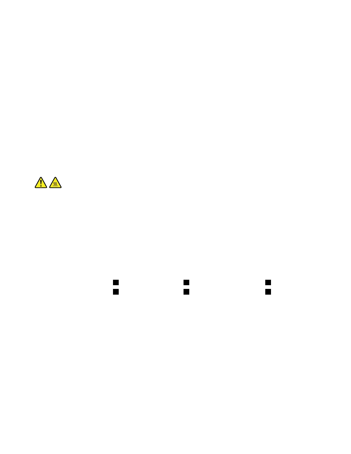
5.Followthefollowingsequencetoremovethefourscrewsthatsecuretheheatsinkandfanassembly
tothesystemboard:
a.Partiallyremovescrew1,thenfullyremovescrew2,andthenfullyremovescrew1.
b.Partiallyremovescrew3,thenfullyremovescrew4,andthenfullyremovescrew3.
Note:Carefullyremovethefourscrewstoavoidanypossibledamagetothesystemboard.Thefour
screwscannotberemovedfromtheheatsinkandfanassembly.
86P320UserGuide

 Loading...