Electrical installation
Motor connection
4
51
MA 13.0001 DE-EN DE/EN 2.0
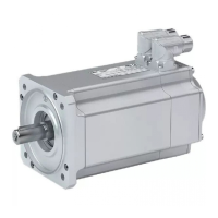
4.4 Motor connection
X3 motor connection
Pin No. Designation Specification
1U
Motor phases
Fundamental wave in
case of overload for 2 s
up to 32 A
eff
approx. 0 V ... 27 V
eff
2 V 0 V ... 13 A
eff
3 W 0 Hz ... 200 Hz
4 BR+
Brake
24V DC
5 BR- 0V
Terminal data
Max. conductor
cross-section
Tightening torque
Screw drive
Cable [mm
2
] [AWG] [Nm] [lb-in]
Flexible
7mm
2.5 12 0.5 ... 0.6 4.4 ... 5.3 Slot 0.6 x 3.5
With wire end
ferrule
Stop!
The brake is supplied by the control voltage at X2. In order to ensure
the trouble-free operation of the brake, the control voltage has to
be in the tolerance range of the brake used!
 Loading...