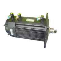
Do you have a question about the Lenze PROFINET 9400 and is the answer not in the manual?
Records changes and updates to the manual across different versions.
Explains formatting, symbols, and writing styles used in the manual for clarity.
Defines key terms and acronyms essential for understanding technical content.
Details signal words and symbols for safety and important information.
Provides essential safety guidelines and notes for using Lenze drive and automation components.
Details safety measures specific to the device and its intended applications.
Outlines potential risks and hazards associated with the device that remain even with safety measures.
Defines the intended use and limitations of the communication module.
Explains how to identify the module's type designation and hardware/software versions.
Lists and describes the key features and functionalities of the communication module.
Identifies and describes the module's connectors, ports, and LEDs for diagnostics.
Provides general specifications, operating conditions, and approvals for the module.
Details protocol-specific data structures and formats used by the module.
Specifies the time delays introduced by the module's integrated 2-port switch.
Explains the protective insulation measures and electrical safety aspects of the device.
Provides physical dimensions and mounting information for the communication module.
Covers the physical mounting, assembly, and disassembly procedures for the communication module.
Details wiring, connections, EMC guidelines, and network topology for electrical setup.
Specifies checks and preparations required before the first power-up of the device.
Guides on setting up the PROFINET IO controller for communication with the module.
Explains how to assign a unique station name for PROFINET network addressing.
Details the process of configuring IP addresses, subnet masks, and gateway addresses.
Describes how to establish remote communication using the Lenze engineering software.
Covers the procedure for the first power-up and establishing communication.
Explains the PROFINET Shared Device feature for accessing a device with multiple controllers.
Details the Media Redundancy Protocol for network fault tolerance.
Explains the different communication channels for process and parameter data transfer.
Guides on mapping Process Data Objects (PDOs) for data exchange configuration.
Describes the acyclic channel used for parameter data exchange based on PROFIdrive.
Details the step-by-step process of acyclic data communication between controller and device.
Explains the format and structure of the PROFINET data frames used for communication.
Explains the process of reading parameters, including request structure and responses.
Explains the process of writing parameters, including request structure and responses.
Lists error codes, their meanings, and descriptions for PROFINET communication errors.
Explains how to ensure data integrity during simultaneous read/write operations.
Describes the PROFIsafe protocol for safe data transfer and its usage with safety modules.
Details how the system detects and responds to PROFINET communication interruptions.
Explains how communication errors between the module and drive are handled.
Provides an overview of all LED status displays for diagnostics and troubleshooting.
Explains the status indications provided by the MS, ME, and DE LEDs.
Explains the status indications provided by the BS and BE LEDs for fieldbus communication.
Describes the status LEDs on the RJ45 sockets indicating PROFINET connection status.
Guides on using the Lenze »Engineer« software for diagnosing the PROFINET bus status.
Explains how diagnostic data and alarm messages are transmitted and displayed.
Offers a summarized list of PROFINET error numbers, names, and their corresponding responses.
Details causes, remedies, and responses for various PROFINET error messages.
Lists communication-relevant parameters of the base Servo Drive 9400 device.
Details parameters specific to the PROFINET communication module in slot MXI1.
Details parameters specific to the PROFINET communication module in slot MXI2.
Explains how to interpret the columns and entries in the parameter attribute table.
| Product Series | 9400 |
|---|---|
| Category | Servo Drives |
| Communication Protocol | PROFINET |
| Protection Class | IP20 |
| Output Current | Up to 180A |
| Control Modes | Speed control, Torque control, Positioning control |
